1 Line Electrical Drawing
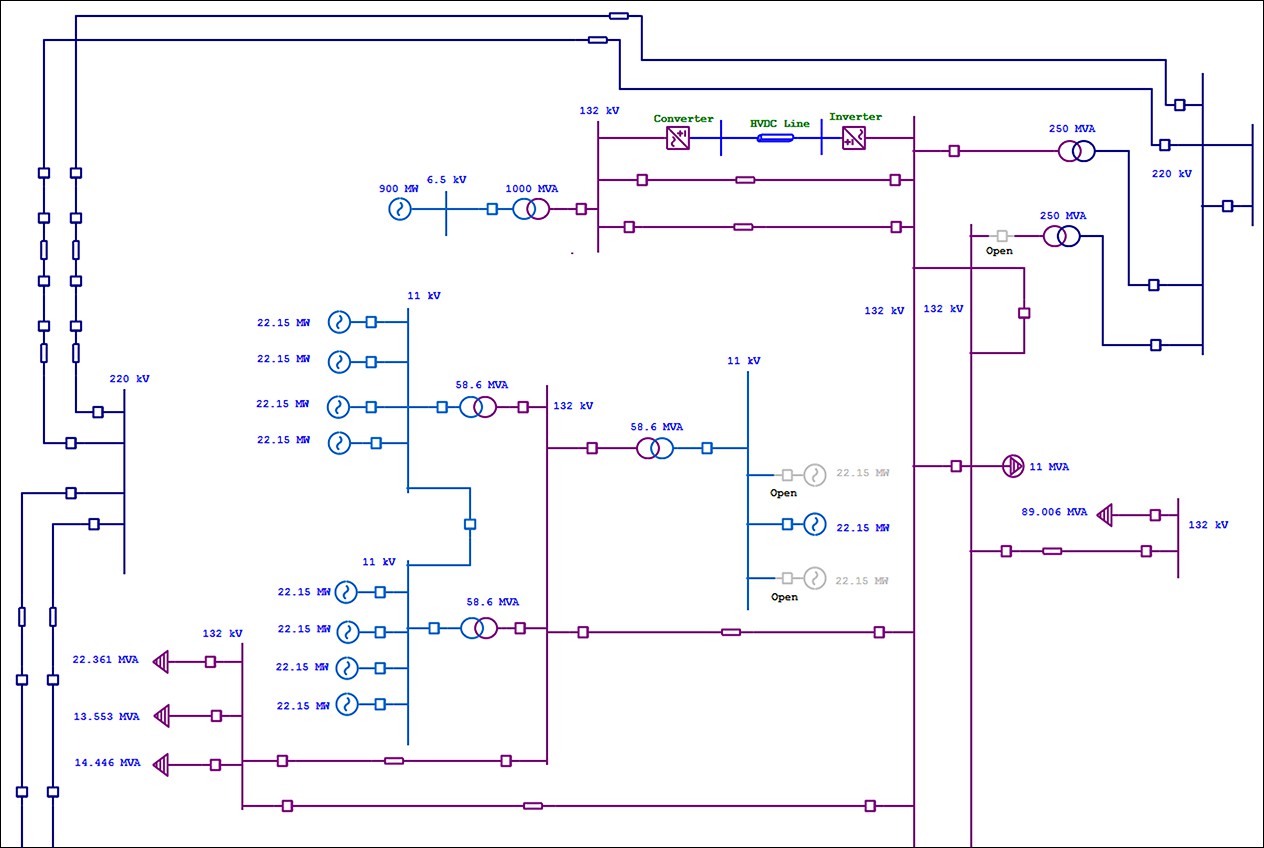
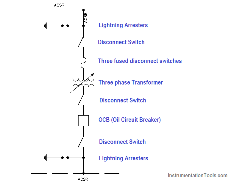
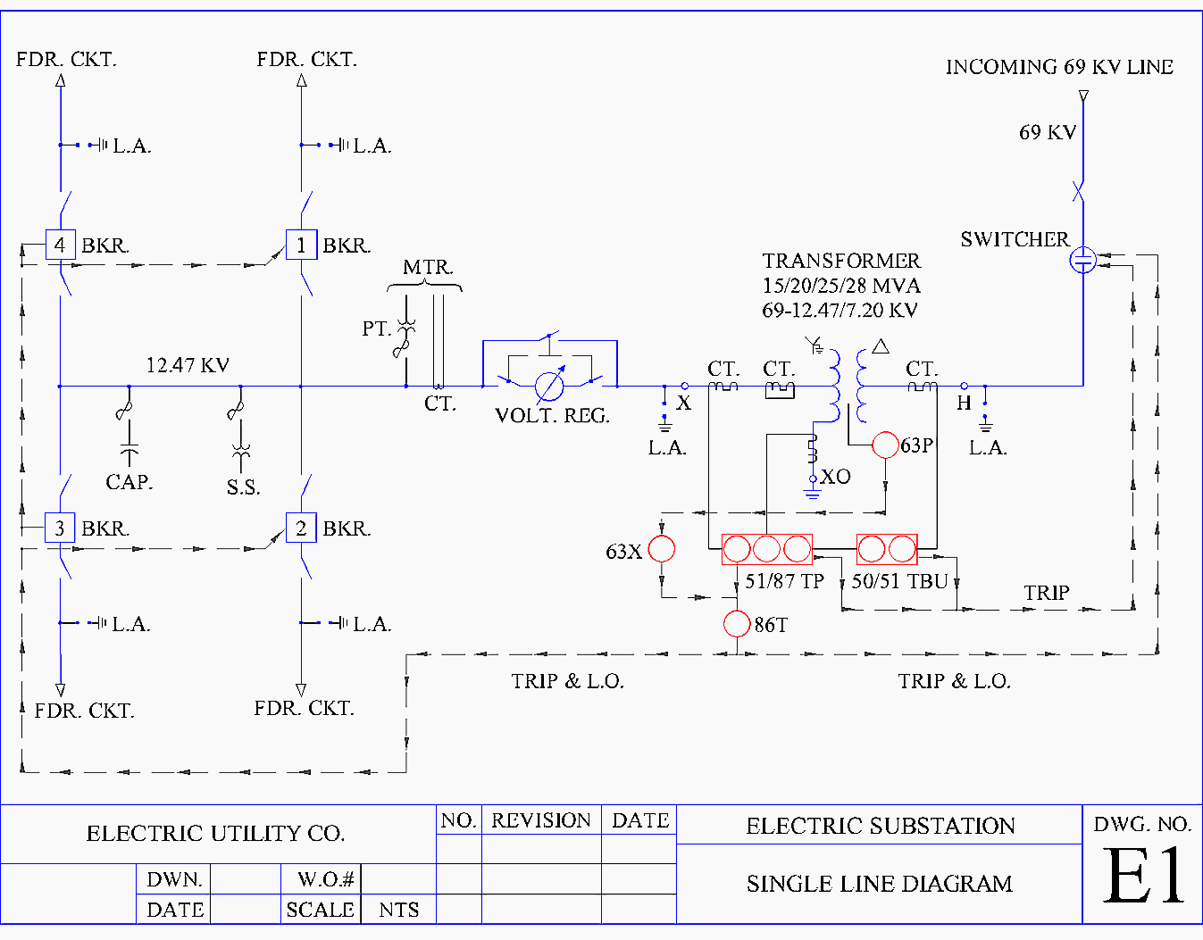
1 Line Electrical Drawing - Ladder diagram or line diagram. Single line diagrams are electrical drawings that provide a basic visual guide to an electrical system detailing various nodes and interconnections which often serve as a base reference for further systems analysis. It is a graphical representation of a circuit or. This isn’t just any 1 line diagram, this one is completely integrated with powercalc’s 7 million+ equations. We will looking a normal set of plans o. Difference between single line diagram (sld ) and three line diagram. “a diagram which shows, by means of single lines and graphic symbols, the course of an electric circuit or system of circuits and the component devices or parts used therein.” Web we usually depict the electrical distribution system by a graphic representation called a single line diagram (sld). Basics 9 4.16 kv pump schematic : The following components comprise a simplified version of a power system, listed in sequential physical order from the generator location to the load:
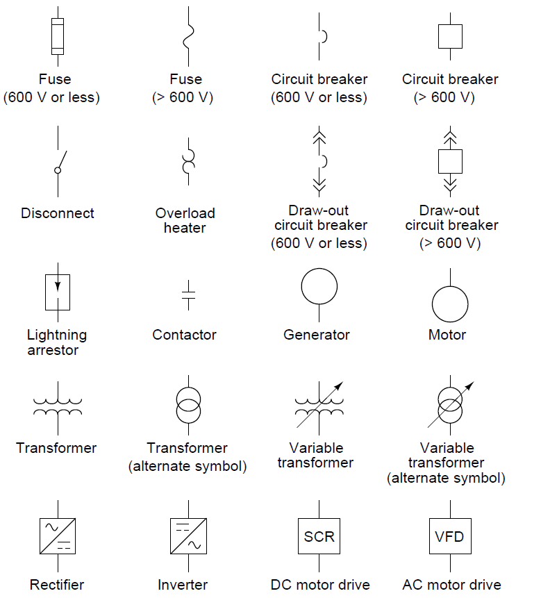
A function block diagram, although it can represent the connection of physical devices, is meant to show a logical connection. Within a few weeks, powercalc will publish its latest application: Web by the end of this video will completely understand the ideals of the one line diagram from a electrical perspective. Web this electrical one line diagram is the primary reference for maintenance and operations for lockout/tagout procedures, as well as for any engineering power system studies. It differs from other diagrams because, in the case of the single line diagram, each circuit is represented by a single line, in which all the conductors of the corresponding section are represented. In this post, i will show why you need an sld and how to make it. Typical electrical drawing symbols and conventions. Difference between single line diagram (sld ) and three line diagram. Electrical power grids primarily consist of. This isn’t just any 1 line diagram, this one is completely integrated with powercalc’s 7 million+ equations.
Typical electrical drawing symbols and conventions. This isn’t just any 1 line diagram, this one is completely integrated with powercalc’s 7 million+ equations. Web by the end of this video will completely understand the ideals of the one line diagram from a electrical perspective. Get ready for the first ever fully automatic, graphic 1 line diagram. Web this electrical one line diagram is the primary reference for maintenance and operations for lockout/tagout procedures, as well as for any engineering power system studies. One line may even represent multiple conductors with other devices between them. Electrical power grids primarily consist of. Within a few weeks, powercalc will publish its latest application: A single line can show all or part of a system. Ladder diagram or line diagram.
Electrical SingleLine Diagram Intelligent One Line Diagram ETAP
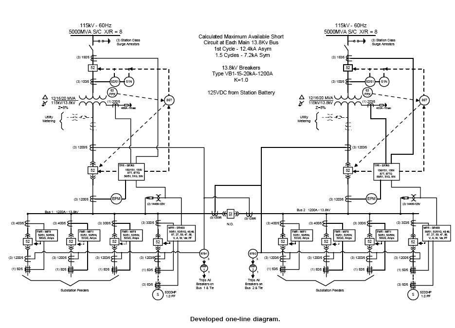
1 line diagram with short circuit or fault current calculation. It is a graphical representation of a circuit or. Web in electrical engineering, a single line diagram is a simplified representation of an electrical power system or electrical grid that shows the flow of electricity through the system. In this post you’ll learn what is single line diagram and why.
Electrical SingleLine Diagram Electrical OneLine Diagram ETAP
Transmission, distribution, and power transformers are also three phases. This isn’t just any 1 line diagram, this one is completely integrated with powercalc’s 7 million+ equations. A block diagram is a type of electrical drawings that represents the principle components of a complex system in the form of blocks interconnected by lines that represent their relation. A function block diagram,.
how to prepare electrical single line diagram Wiring Diagram and
Web by the end of this video will completely understand the ideals of the one line diagram from a electrical perspective. 1 line diagram with short circuit or fault current calculation. Transmission, distribution, and power transformers are also three phases. So easy, in fact, practically anyone can use it. A single line can show all or part of a system.

How To Read Electrical Line Diagrams Wiring Digital and Schematic
This isn’t just any 1 line diagram, this one is completely integrated with powercalc’s 7 million+ equations. The following components comprise a simplified version of a power system, listed in sequential physical order from the generator location to the load: Web we usually depict the electrical distribution system by a graphic representation called a single line diagram (sld). Web by.
Singleline Electrical Diagrams Electric Power Measurement and
Ladder diagram or line diagram. It is a graphical representation of a circuit or. A block diagram is a type of electrical drawings that represents the principle components of a complex system in the form of blocks interconnected by lines that represent their relation. [1] [2] a single line in the diagram typically corresponds to more than one physical conductor:.
Electrical Single Line Diagram
Electrical power grids primarily consist of. So easy, in fact, practically anyone can use it. Typical electrical drawing symbols and conventions. Get ready for the first ever fully automatic, graphic 1 line diagram. Ladder diagram or line diagram.

Single Line Diagram of Power Plant Power Systems
Ladder diagram or line diagram. Web by the end of this video will completely understand the ideals of the one line diagram from a electrical perspective. Difference between single line diagram (sld ) and three line diagram. Web in electrical engineering, a single line diagram is a simplified representation of an electrical power system or electrical grid that shows the.

How To Calculate and Draw a Single Line Diagram For The Power System EEP
This condenses the space and complexity of the diagram for simpler troubleshooting. “a diagram which shows, by means of single lines and graphic symbols, the course of an electric circuit or system of circuits and the component devices or parts used therein.” It is used by electricians, engineers, and technicians to understand the electrical components and connections within a system..
Single Line Diagram Symbols Iec
We will looking a normal set of plans o. A single line can show all or part of a system. A function block diagram, although it can represent the connection of physical devices, is meant to show a logical connection. Ladder diagram or line diagram. Within a few weeks, powercalc will publish its latest application:
One Line Electrical Diagram
Within a few weeks, powercalc will publish its latest application: A single line can show all or part of a system. Web we usually depict the electrical distribution system by a graphic representation called a single line diagram (sld). “a diagram which shows, by means of single lines and graphic symbols, the course of an electric circuit or system of.
Difference Between Single Line Diagram (Sld ) And Three Line Diagram.
It differs from other diagrams because, in the case of the single line diagram, each circuit is represented by a single line, in which all the conductors of the corresponding section are represented. The following components comprise a simplified version of a power system, listed in sequential physical order from the generator location to the load: A single line can show all or part of a system. Web we usually depict the electrical distribution system by a graphic representation called a single line diagram (sld).
Single Line Diagrams Are Electrical Drawings That Provide A Basic Visual Guide To An Electrical System Detailing Various Nodes And Interconnections Which Often Serve As A Base Reference For Further Systems Analysis.
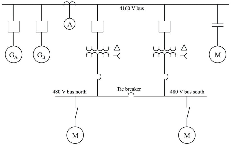
Basics 9 4.16 kv pump schematic : Electrical power grids primarily consist of. In this post, i will show why you need an sld and how to make it. One line may even represent multiple conductors with other devices between them.
Web In Electrical Engineering, A Single Line Diagram Is A Simplified Representation Of An Electrical Power System Or Electrical Grid That Shows The Flow Of Electricity Through The System.
We will looking a normal set of plans o. Our electrical power systems primarily contain three phases of ac circuits. Ladder diagram or line diagram. It is a graphical representation of a circuit or.
[1] [2] A Single Line In The Diagram Typically Corresponds To More Than One Physical Conductor:
So easy, in fact, practically anyone can use it. “a diagram which shows, by means of single lines and graphic symbols, the course of an electric circuit or system of circuits and the component devices or parts used therein.” Get ready for the first ever fully automatic, graphic 1 line diagram. Typical electrical drawing symbols and conventions.