778 Draw The Shear And Moment Diagrams For The Beam
778 Draw The Shear And Moment Diagrams For The Beam - This problem has been solved! Web this problem has been solved! Web shear and moment diagrams are graphs which show the internal shear and bending moment plotted along the length of the beam. Draw the shear force, axial force and bending moment diagrams. Web shear/moment diagrams are graphical representations of the internal shear force and bending moment along the whole beam. (b) determine the magnitude and location of the maximum absolute value of the bending moment. Deflection at the endpoint, ∂ = p a 2 6 e i ( 3 l − a); You'll get a detailed solution from a subject matter expert that helps you learn core concepts. Draw the shear and moment diagrams for the beam. We know for a cantilever beam (as shown in the figure (i)) l a.
You'll get a detailed solution from a subject matter expert that helps you learn core concepts. Web shear/moment diagrams are graphical representations of the internal shear force and bending moment along the whole beam. Shear and moment diagrams and formulas are excerpted from the western woods use book, 4th edition, and are provided herein as a courtesy of western wood products association. Draw the shear force, axial force and bending moment diagrams. Web the equation also suggests that the slope of the moment diagram at a particular point is equal to the shear force at that same point. Write shear and moment equations for the beams in the following problems. Draw the shear and moment diagrams for the beam | chegg.com. Web you will be fully competent in drawing shear force and bending moment diagrams for statically determinate beams and frames. Start at one end, (point a), of the beam and work toward the other end. This problem has been solved!
Web figures 1 through 32 provide a series of shear and moment diagrams with accompanying formulas for design of beams under various static loading conditions. The beginning, end, or change of a load pattern. Not the question you’re looking for? This problem has been solved! Skyciv beam tool guides users along a professional beam calculation workflow, culminating in the ability to view and determine if they comply with your region's design codes. Web in order to construct shear and moment diagrams for a beam, first, determine the reactive forces and couple moments acting on the beam, and resolve all the forces into components acting perpendicular and parallel to the beam’s axis. Q 5) draw the shear and moment diagrams for the beam. Web shear and moment diagrams are graphs which show the internal shear and bending moment plotted along the length of the beam. Civil engineering questions and answers. Divide the beam (of length l) into n segments.

Shear Force and Bending Moment diagram of Beam with Triangular Load
Start at one end, (point a), of the beam and work toward the other end. You'll get a detailed solution from a subject matter expert that helps you learn core concepts. This problem has been solved! 7.3k views 2 years ago statics. View the full answer answer.
draw the shear and moment diagrams for the beam chegg
Also, draw shear and moment diagrams, specifying values at all change of loading positions and at points of zero shear. This problem has been solved! Web in order to construct shear and moment diagrams for a beam, first, determine the reactive forces and couple moments acting on the beam, and resolve all the forces into components acting perpendicular and parallel.

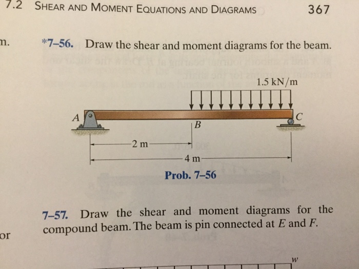
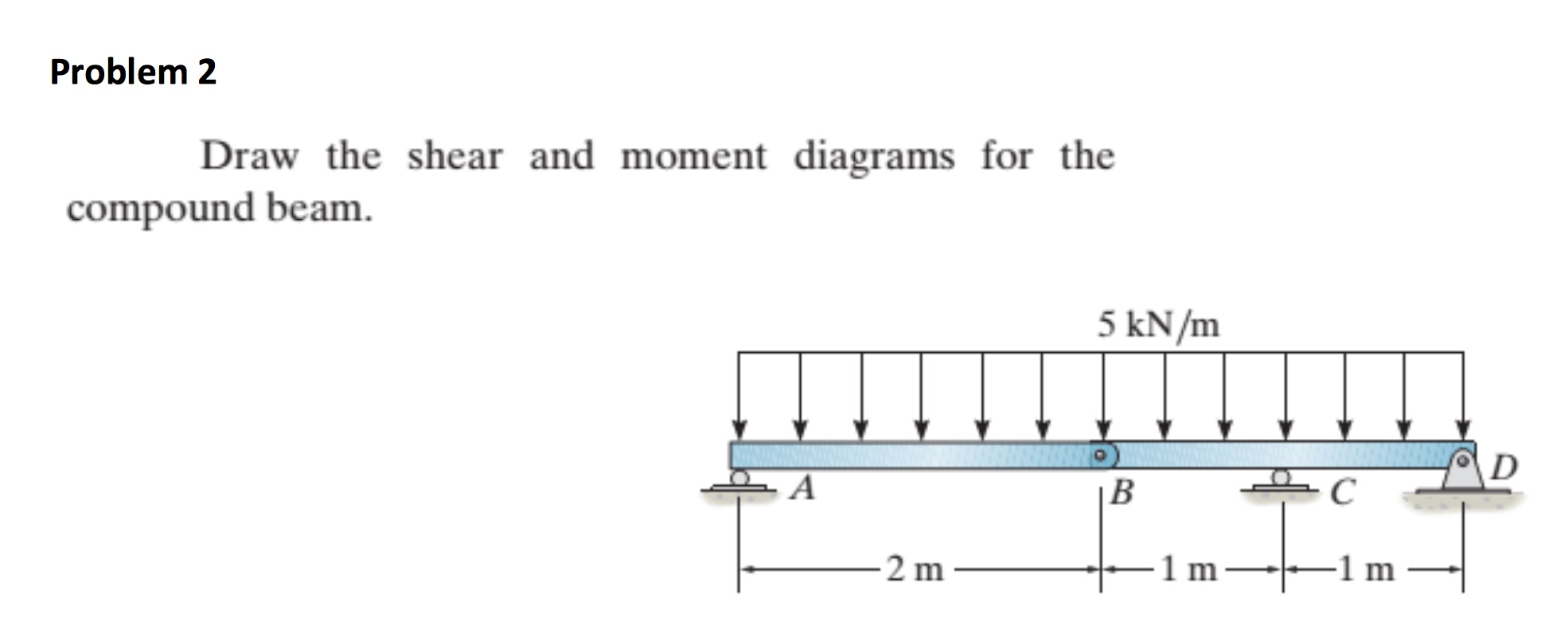
Draw the shear and moment diagrams for the beam.
You'll get a detailed solution from a subject matter expert that helps you learn core concepts. Draw the shear and moment diagrams for the beam | chegg.com. Civil engineering questions and answers. Divide the beam (of length l) into n segments. Neglect the mass of the beam in each problem.

Learn How To Draw Shear Force And Bending Moment Diagrams Engineering
Not the question you’re looking for? Civil engineering questions and answers. Web shear and moment diagrams are graphs which show the internal shear and bending moment plotted along the length of the beam. See our solution for question 70p from chapter 7 from hibbeler's engineering mechanics. They allow us to see where the maximum loads occur so that we can.

Shear and moment diagrams geekloki
Web our calculator generates the reactions, shear force diagrams (sfd), bending moment diagrams (bmd), deflection, and stress of a cantilever beam or simply supported beam. Write shear and moment equations for the beams in the following problems. The beginning, end, or change of a load pattern. 92k views 3 years ago statics. You'll get a detailed solution from a subject.
draw the shear and moment diagrams for the beam chegg
Civil engineering questions and answers. Start at one end, (point a), of the beam and work toward the other end. Assume that the flexural rigidity is a multiple of ei and differs for each member as shown in the figure. Determine all the reactions on the beam. Q5) draw the shear and moment diagrams for the beam.

Solved Draw the shear and moment diagrams for the beam
7.3k views 2 years ago statics. Web this problem has been solved! Deflection at the endpoint, ∂ = p a 2 6 e i ( 3 l − a); We know for a cantilever beam (as shown in the figure (i)) l a. In each problem, let x be the distance measured from left end of the beam.
Solved Draw the shear and moment diagrams for the beam.
They allow us to see where the maximum loads occur so that we can optimize the design to prevent failures and reduce the overall weight and cost of the structure. Civil engineering questions and answers. (b) determine the magnitude and location of the maximum absolute value of the bending moment. Shear and moment diagrams and formulas are excerpted from the.

Solved Draw the shear and moment diagrams for the beam.
You'll get a detailed solution from a subject matter expert that helps you learn core concepts. The beginning, end, or change of a load pattern. Equation 6.1 suggests the following expression: Write shear and moment equations for the beams in the following problems. Civil engineering questions and answers.

Learn How To Draw Shear Force And Bending Moment Diagrams Engineering
Draw the shear force, axial force and bending moment diagrams. Web shear/moment diagrams are graphical representations of the internal shear force and bending moment along the whole beam. Web a free body diagram of a section cut transversely at position \(x\) shows that a shear force \(v\) and a moment \(m\) must exist on the cut section to maintain equilibrium..
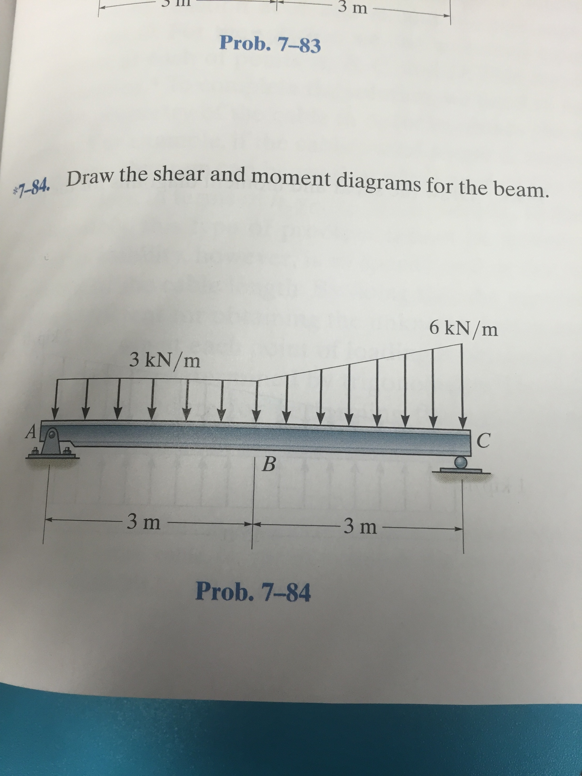
Draw The Shear And Moment Diagrams For The Beam.
Web in order to construct shear and moment diagrams for a beam, first, determine the reactive forces and couple moments acting on the beam, and resolve all the forces into components acting perpendicular and parallel to the beam’s axis. 7.3k views 2 years ago statics. Civil engineering questions and answers. Also, draw shear and moment diagrams, specifying values at all change of loading positions and at points of zero shear.
Web Shear And Moment Diagrams Are Graphs Which Show The Internal Shear And Bending Moment Plotted Along The Length Of The Beam.
Web you will be fully competent in drawing shear force and bending moment diagrams for statically determinate beams and frames. Draw the shear and moment diagrams for the beam | chegg.com. You'll get a detailed solution from a subject matter expert that helps you learn core concepts. Web a free body diagram of a section cut transversely at position \(x\) shows that a shear force \(v\) and a moment \(m\) must exist on the cut section to maintain equilibrium.
Web This Problem Has Been Solved!
Q5) draw the shear and moment diagrams for the beam. You'll get a detailed solution from a subject matter expert that helps you learn core concepts. Civil engineering questions and answers. Skyciv beam tool guides users along a professional beam calculation workflow, culminating in the ability to view and determine if they comply with your region's design codes.
Web Problem 7.78 (M For The Beam And Loading Shown, (A) Draw The Shear And Bending Moment Diagrams, (B) Determine The Magnitude And Location Of The Maximum Absolute Value Of The Bending Moment.
We are given a simply supported beam with multiple forces and moment acting on it. Draw the shear and moment diagrams for the beam. [latex]\delta m=\int v (x)dx [/latex] (equation 6.2) equation 6.2 states that the change in moment equals the area under the shear diagram. Web 11k views 2 years ago statics.