An Engineering Drawing Shows The
An Engineering Drawing Shows The - Materials, finishes, machining operations, and dimensions of a component. Read this first to find out crucial information about the drawing, including: The symbols used for each hole and how they are shown on engineering drawings. The purpose is to convey all the information necessary for manufacturing a product or a part. Engineering drawings are a collection of standardized language, symbols, and graphic patterns to convey all the information needed to manufacture a product or part. Study with quizlet and memorize flashcards containing terms like assembly drawing, detail drawing, dimensioning and more. The video below covers the fundamentals, including the different types of views, first and third angle projection methods, dimensioning, tolerancing, best practices when creating drawings. Web engineering drawings are key tools that engineers use to communicate, but deciphering them isn’t always straightforward. A freehand thick line, and. Web any engineering drawing should show everything:
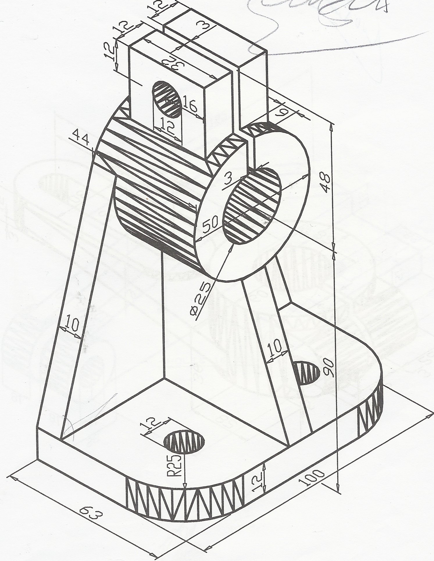
Read this first to find out crucial information about the drawing, including: Web read about engineering fits, basic terminology, how to select a proper fit and how to show fits on engineering drawings. Materials, finishes, machining operations, and dimensions of a component. The video below covers the fundamentals, including the different types of views, first and third angle projection methods, dimensioning, tolerancing, best practices when creating drawings. However, if the object in figure 2 had a hole on the back. This is a complete guide to the types of holes found in machining. Study with quizlet and memorize flashcards containing terms like assembly drawing, detail drawing, dimensioning and more. Dimensions, tolerances, materials, and finishes of a component. Web an engineering drawing shows the: A freehand thick line, and.
It is the universal “engineering technology language” in. Read this first to find out crucial information about the drawing, including: Web october 14, 2022 / 10 minutes of reading. What the difference is between counterbore and countersink holes. Materials, finishes, machining operations, and dimensions of a component. A common use is to specify the geometry necessary for the construction of a component and is called a detail drawing. If the isometric drawing can show all details and all dimensions on one drawing, it is ideal. A freehand thick line, and. Web engineering drawings, also known as mechanical drawings, manufacturing blueprints, drawings, etc., are technical drawings that show the shape, structure, dimensions, tolerances, accuracy, and other requirements of a part in the form of a plan. Engineering drawings are a collection of standardized language, symbols, and graphic patterns to convey all the information needed to manufacture a product or part.
Engineering Drawing Views & Basics Explained Fractory
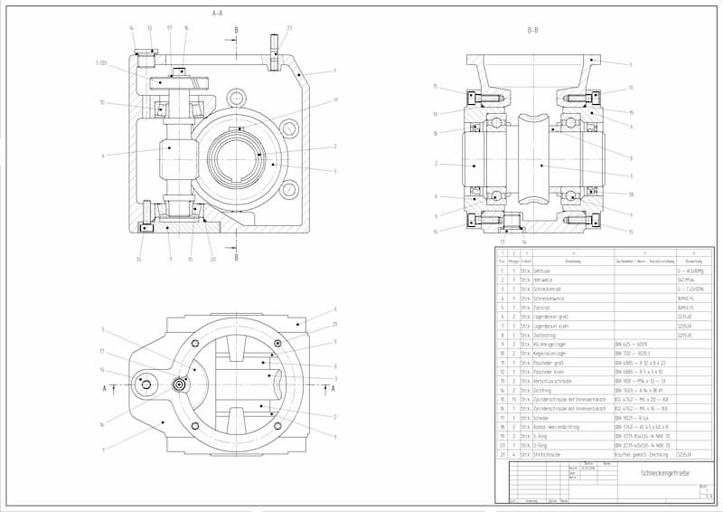
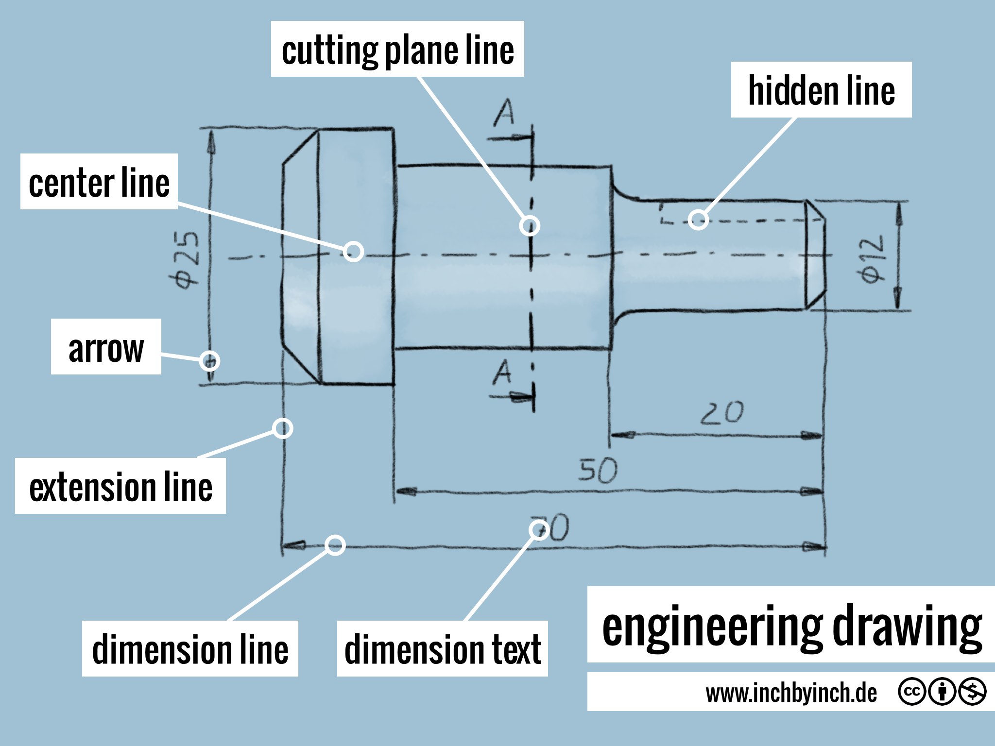
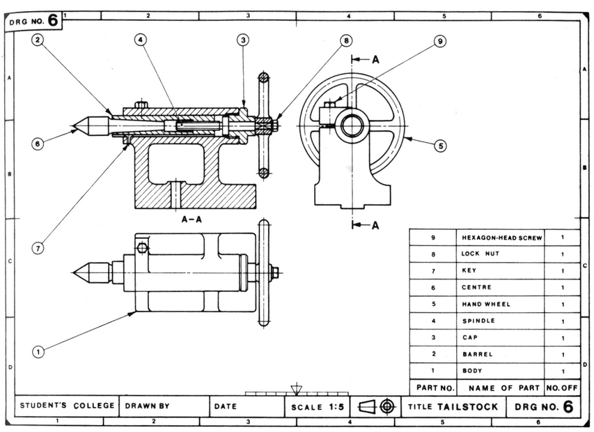
Why not just use a 3d model? Dimensions, tolerances, cost, and sales or use volume of a component. It is generally used by engineers,. Check the title block for basic information about the drawing. Section line, section reference arrow, section reference letters, hatch.
Download How To Read Basic Engineering Drawing Guide Pictures
1.2 historical background and evolution. 1.1 definition and overview of engineering drawing. Materials, finishes, machining operations, and dimensions of a component. A common use is to specify the geometry necessary for the construction of a component and is called a detail drawing. Dimensions, tolerances, materials, and finishes of a component.
INCH Technical English engineering drawing
Materials, finishes, machining operations, and dimensions of a component. Web an engineering drawing shows the: Materials, finishes, machining operations, and dimensions of a component. Web any engineering drawing should show everything: Why not just use a 3d model?

Mechanical Engineer Drawing at GetDrawings Free download
It is generally used by engineers,. Materials, finishes, machining operations, and dimensions of a component. Web october 14, 2022 / 10 minutes of reading. Dimensions, tolerances, cost, and sales or use volume of a component. If the isometric drawing can show all details and all dimensions on one drawing, it is ideal.

Types Of Dimensions In Engineering Drawing at GetDrawings Free download
Dimension and extension lines are. Web october 14, 2022 / 10 minutes of reading. Web 18.06.2020 by andreas velling. It is more than simply a drawing, it is a graphical language that communicates ideas and information. However, if the object in figure 2 had a hole on the back.
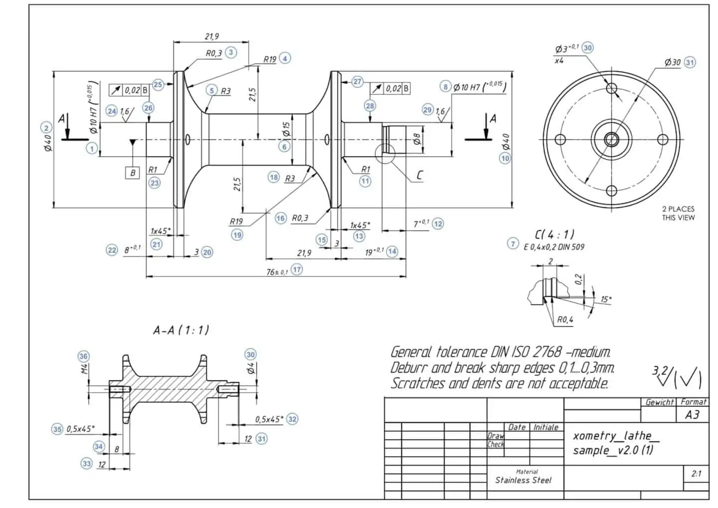
How To Prepare A Perfect Technical Drawing Xometry Europe
Engineering drawings are a collection of standardized language, symbols, and graphic patterns to convey all the information needed to manufacture a product or part. Web the picture below shows how our object would be represented in the engineering drawing. What the difference is between counterbore and countersink holes. A) dimensions, tolerances, materials, and finishes of a component. Check the title.
Lecture Notes Engineering Drawing Part 5
1.3 importance in various fields like mechanical engineering, civil engineering, etc. One can pack a great deal of information into an isometric drawing. Web 18.06.2020 by andreas velling. Materials, finishes, machining operations, and dimensions of a component. Dimensions, tolerances, materials, and finishes of a component.

Mechanical Engineering Drawing and Design, Everything You Need To Know
Web an engineering drawing shows the: Web engineering drawings (aka blueprints, prints, drawings, mechanical drawings) are a rich and specific outline that shows all the information and requirements needed to manufacture an item or product. Break lines come in two forms: If the isometric drawing can show all details and all dimensions on one drawing, it is ideal. Dimension and.
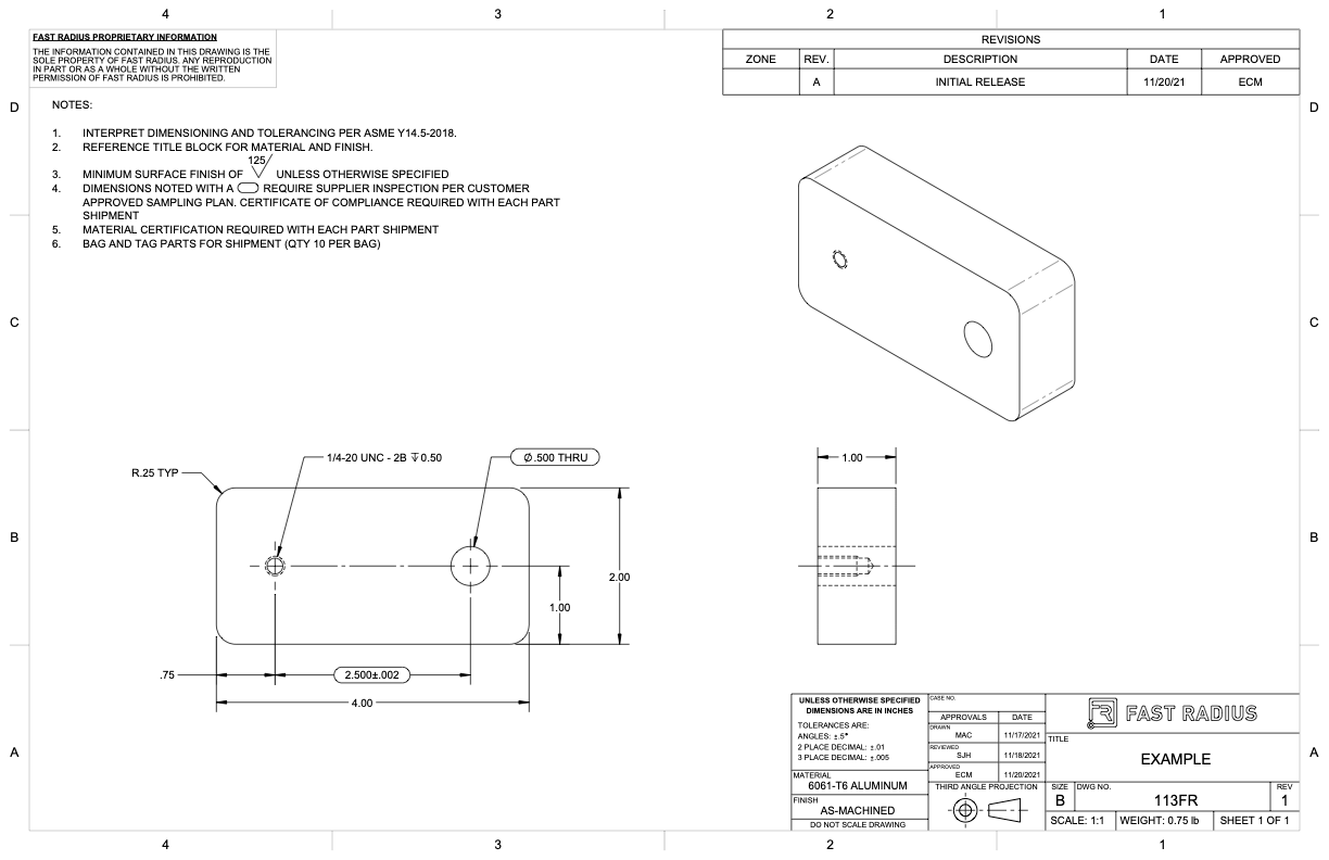
What to Include in Your Engineering Drawing Fast Radius
Cost, dimensions, and machining operations for a component. The title block appears either at the top or bottom of an engineering drawing. What the difference is between counterbore and countersink holes. A complete understanding of the object should be possible from the drawing. 1.3 importance in various fields like mechanical engineering, civil engineering, etc.
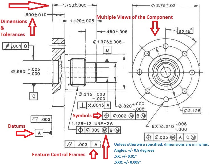
Engineering Drawings & GD&T For the Quality Engineer
Web break lines are used to show where an object is broken to save drawing space or reveal interior features. Web read about engineering fits, basic terminology, how to select a proper fit and how to show fits on engineering drawings. If the isometric drawing can show all details and all dimensions on one drawing, it is ideal. Web any.
Dimension And Extension Lines Are.
A) dimensions, tolerances, materials, and finishes of a component. Engineering drawings are a collection of standardized language, symbols, and graphic patterns to convey all the information needed to manufacture a product or part. Study with quizlet and memorize flashcards containing terms like assembly drawing, detail drawing, dimensioning and more. These drawings are essentially the blueprints or plans for manufacturing a wide array of products and structures.
This Is A Complete Guide To The Types Of Holes Found In Machining.
Web any engineering drawing should show everything: Engineering drawings are also known as mechanical drawings, manufacturing blueprints and drawings. Web a type of engineering drawing that shows the most complete drawing produced. 545k views 3 years ago orthographic projections.
We Will Go Step By.
The main elements of the section view are: Web an engineering drawing shows the: Types of the engineering drawing projection methods. Web engineering drawings (aka blueprints, prints, drawings, mechanical drawings) are a rich and specific outline that shows all the information and requirements needed to manufacture an item or product.
It Is Generally Used By Engineers,.
Web engineering drawings, also known as mechanical drawings, manufacturing blueprints, drawings, etc., are technical drawings that show the shape, structure, dimensions, tolerances, accuracy, and other requirements of a part in the form of a plan. Read this first to find out crucial information about the drawing, including: Web an engineering drawing shows the: Materials, finishes, machining operations, and dimensions of a component.