Centerline In Drawing
Centerline In Drawing - Web because you may have a drawing view with many centerlines (through various features that lend themselves to the use of centerlines), and you may wish to identify the centerline that represents the center of the part itself. In the graphics window, click a feature to start the centerline. Adjust the length of the centerlines by clicking and dragging the grip points at the end of the centerline. On the ribbon, click annotate tab symbols panel centerline. Web center lines denote a circular feature such as a shaft or a hole. Their basic purpose is to show circular/cylindrical features in a drawing, which are found in abundance in mechanical parts. Web you can manually apply four types of centerlines and center marks to individual features or parts in a drawing view. • click anywhere on a center line except the handle to rotate the line. Web manually add a centerline. Web to establish the centerline, do one of the following:
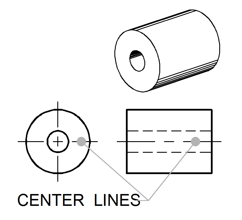
On the ribbon, click annotate tab symbols panel centerline. These lines are drawn as long, thin dashed lines and are used to indicate the center point of cylindrical features, such as holes or shafts. Web what drawings standards are you working to, and what do you think center lines mean/get you from a dimensioning & tolerancing point of view? To create a center line, this command allows you to create a center line for a circular element. Web questions about using centerlines are so common that we wanted to post some information about why they are used, and how they impact more than.more. You can insert centerlines into drawing views automatically or manually. A rectangular feature seen on an elevation of a drawing could be identified either as a circular feature or a rectangular feature. The centerline is also used to place the centerpoints of new windows on the construction plan. Web on drawings, centerlines are annotations that mark the centers of circles and describe their geometric size. Their basic purpose is to show circular/cylindrical features in a drawing, which are found in abundance in mechanical parts.
This blog will show you two different options for auto insertion which generate two types of centerlines on your drawings. Common examples of such features include bolt holes, pins, discs, etc. • click anywhere on a center line except the handle to rotate the line. Web on drawings, centerlines are annotations that mark the centers of circles and describe their geometric size. Web center lines are an important element of engineering drawings that are used to represent the axis of symmetry for a part or assembly. The center line is the method of quickly identifying the shape. A rectangular feature seen on an elevation of a drawing could be identified either as a circular feature or a rectangular feature. Web setting up your drawings to automatically add centerlines is quick and easy. Web center lines denote a circular feature such as a shaft or a hole. • click on an arc symmetry line to extend it (if the arcs have the same center point).

Centerlines and Center Marks AutoCAD 2017 Tutorial AutoCAD YouTube
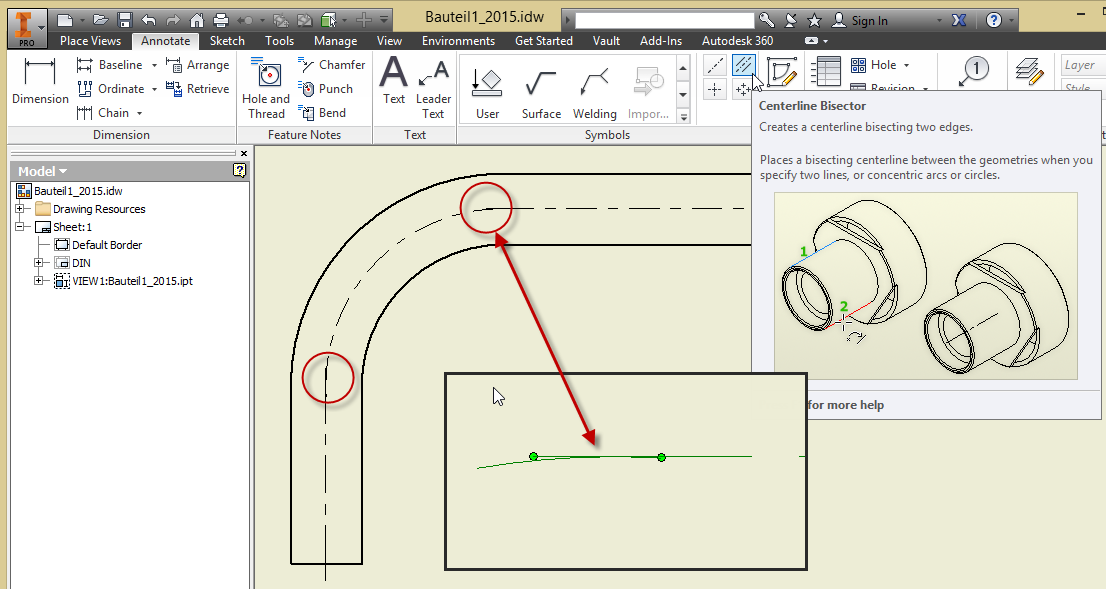
While holding the shift key, select two edges or concentric arcs. Web centerlines are annotations that mark circle centers and describe the geometry size on drawings. Their basic purpose is to show circular/cylindrical features in a drawing, which are found in abundance in mechanical parts. The solidworks software prevents duplicate centerlines. To create a center line, this command allows you.

2020 Drawing Center Lines for an Orthographic Drawing YouTube
This blog will show you two different options for auto insertion which generate two types of centerlines on your drawings. The centerline is also used to place the centerpoints of new windows on the construction plan. Web to establish the centerline, do one of the following: Web you can add center lines and symmetry lines to your drawing. Web centerlines.
How to create centerlines of sweeped objects effectively in Inventor
Depending on the 3d geometry all of your centerlines could be correct. You can insert centerlines into drawing views automatically or manually. While holding the shift key, select two edges or concentric arcs. This is a discussion question we received. Web centerlines are annotations that mark circle centers and describe the geometry size on drawings.

Autodesk Inventor How to Create a Centerline for Drawing Views YouTube
Web centerlines are annotations that mark the center between two line segments on a drawing view. Adjust the length of the centerlines by clicking and dragging the grip points at the end of the centerline. That way if things change, your drawing will. Web center lines denote a circular feature such as a shaft or a hole. Web centerlines are.
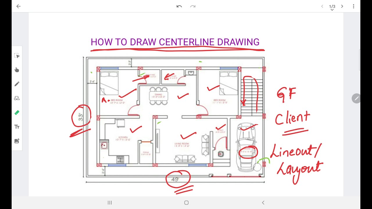
HOW TO PREPARE CENTERLINE DRAWING YouTube
You can insert centerlines into drawing views automatically or manually. The center line is the method of quickly identifying the shape. • click on an arc symmetry line to extend it (if the arcs have the same center point). • click anywhere on a center line except the handle to rotate the line. You can insert centerlines into drawing views.
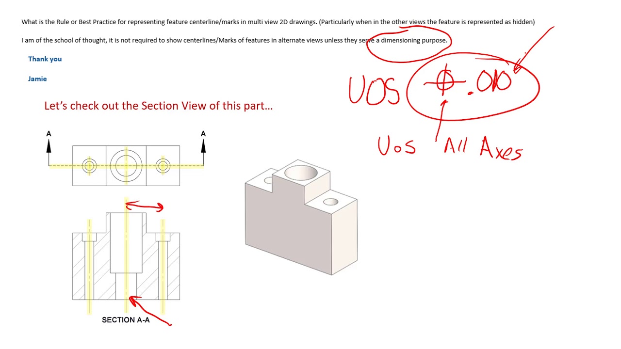
Centerlines on Engineering Drawings and how they should be used
The solidworks software avoids duplicate centerlines. The solidworks software avoids duplicate centerlines. Web centerlines are annotations that mark circle centers and describe the geometry size on drawings. Web solidworks course for beginners: To create a center line, this command allows you to create a center line for a circular element.
Center Lines ToolNotes
Adjust the length of the centerlines by clicking and dragging the grip points at the end of the centerline. You can insert centerlines into drawing views automatically or manually. Web centerlines are annotations that mark circle centers and describe the geometry size on drawings. Web you can create centerlines between parallel curves or through points on a technical drawing by.

PPT Orthographic Drawing PowerPoint Presentation ID3681704
Web you can manually apply four types of centerlines and center marks to individual features or parts in a drawing view. Web to establish the centerline, do one of the following: The solidworks software avoids duplicate centerlines. Web because you may have a drawing view with many centerlines (through various features that lend themselves to the use of centerlines), and.

Adding a Center Line to a Drawing View YouTube
Web you can manually apply four types of centerlines and center marks to individual features or parts in a drawing view. Web to modify center and symmetry lines, • click a center or symmetry line handle and drag it to extend the line. To create centerline between straight lines: To create a center line, this command allows you to create.

Center line plan of residence ground floor plan centerlineplan
You can insert centerlines into drawing views automatically or manually. Adjust the length of the centerlines by clicking and dragging the grip points at the end of the centerline. Web centerlines are one of the most frequently used tools in engineering drawing. Web centerlines are annotations that mark circle centers and describe the geometry size on drawings. Web solidworks course.
The Solidworks Software Avoids Duplicate Centerlines.
These are useful for aligning elements and when adding dimensioning parameters. The centerline is used when dimensioning to locate the centerpoints of appliances and fixtures on nkba drawings. Web center lines denote a circular feature such as a shaft or a hole. Click a second feature to add the centerline.
The Solidworks Software Avoids Duplicate Centerlines.
You can insert centerlines into drawing views automatically or manually. This helps ensure proper installation of plumbing and electrical items. Menu => insert => centerline => 2d centerline. Continue selecting features until all desired features are added.
Common Examples Of Such Features Include Bolt Holes, Pins, Discs, Etc.
These lines are drawn as long, thin dashed lines and are used to indicate the center point of cylindrical features, such as holes or shafts. • click anywhere on a center line except the handle to rotate the line. You can insert centerlines into drawing views automatically or manually. Web you can add center lines and symmetry lines to your drawing.
Web Manually Add A Centerline.
While holding the shift key, select two edges or concentric arcs. On the ribbon, click annotate tab symbols panel centerline. Learn how to add centerlines using your model's sketch. Web solidworks course for beginners: