Chamfer Callout On Drawing
Chamfer Callout On Drawing - If it is not clear that a hole is a thru hole by. Web chamfers, rounds, fillets, and “break edges” are edge features that you may commonly see on your part drawings. Click on the links below to learn more about each gd&t symbol or concept,. Find out the proper way to do a chamfer callout, as well as th… At times, the break edge. Web to add or edit chamfer notes on drawing views. Web you can dimension chamfers in drawings. Web the typical callout will most often be used as part of a repeating pattern such as a bolt hole circle, to identify the hole sizes or angle between the holes. Web the size dimension gives the design size of a feature. Solidwork has a dimension style that is c1 for 45.
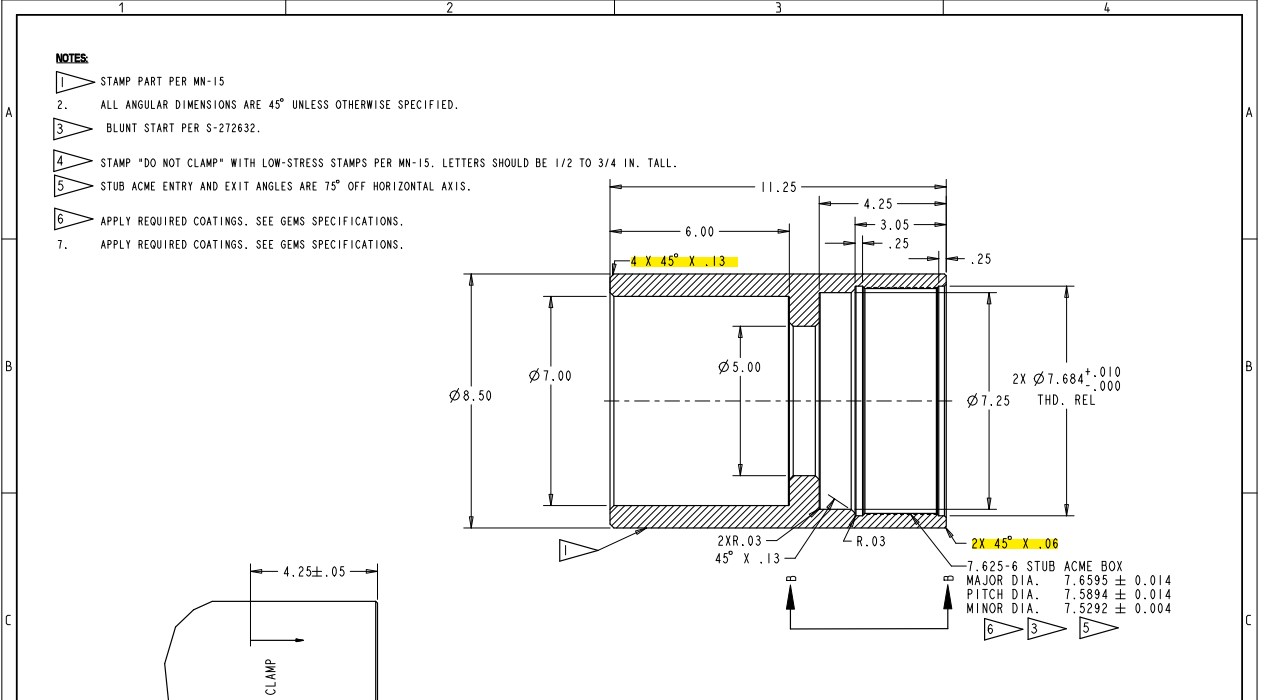
Optical drawings provide a precise definition of your optic for fabrication. Web when i create a shown dimension for a chamfer in a drawing the leader seem to be fixed to an angle or its created with the normal leader option. Web to add or edit chamfer notes on drawing views. In addition to the usual dimension display properties, chamfer dimensions have their own options for leader display, text display,. Web you can draw a rectangle at desired corner and after that a line to create chamfer, then trim (delete) other lines. Web if the chamfer is only part way around the cylinder, then more information is needed, such as where does it begin or end. Web the size dimension gives the design size of a feature. Steps creating a hole or thread callout: At times, the break edge. Use the chamfer command to add a.
Modify text descriptions, precision and tolerance values, leader format, and other details. Y14.5 clearly says a note 1 x 1 or 1 x 45° is allowed. Is it to call out the note with a leader (.25 x 45°) or to add two seperate dimensions (one linear and They are used for a variety of reasons, which. Web when using a leader to call out a chamfer (ie. Web you can dimension chamfers in drawings. Use the chamfer command to add a. Standards allow for a common language to be used between you and the. Web the typical callout will most often be used as part of a repeating pattern such as a bolt hole circle, to identify the hole sizes or angle between the holes. Click on the links below to learn more about each gd&t symbol or concept,.

Steps to add chamfer dimension in 2D drawing SEACAD
Use the chamfer command to add a. Another way is to draw a line where you want the. They are used for a variety of reasons, which. Web you can dimension chamfers in drawings. Web when i create a shown dimension for a chamfer in a drawing the leader seem to be fixed to an angle or its created with.
Solved Multiple chamfers on drawings PTC Community
Use the chamfer command to add a. Modify text descriptions, precision and tolerance values, leader format, and other details. Web when using a leader to call out a chamfer (ie. Click on the links below to learn more about each gd&t symbol or concept,. Web if the chamfer is only part way around the cylinder, then more information is needed,.
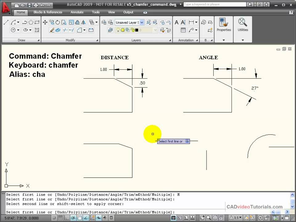
AutoCAD Tutorial Using the CHAMFER Command YouTube
Web what is the standard for a callout of a chamfer feature? Web when i create a shown dimension for a chamfer in a drawing the leader seem to be fixed to an angle or its created with the normal leader option. Web what is the correct way to call out a 45 degree chamfer? Use the chamfer command to.
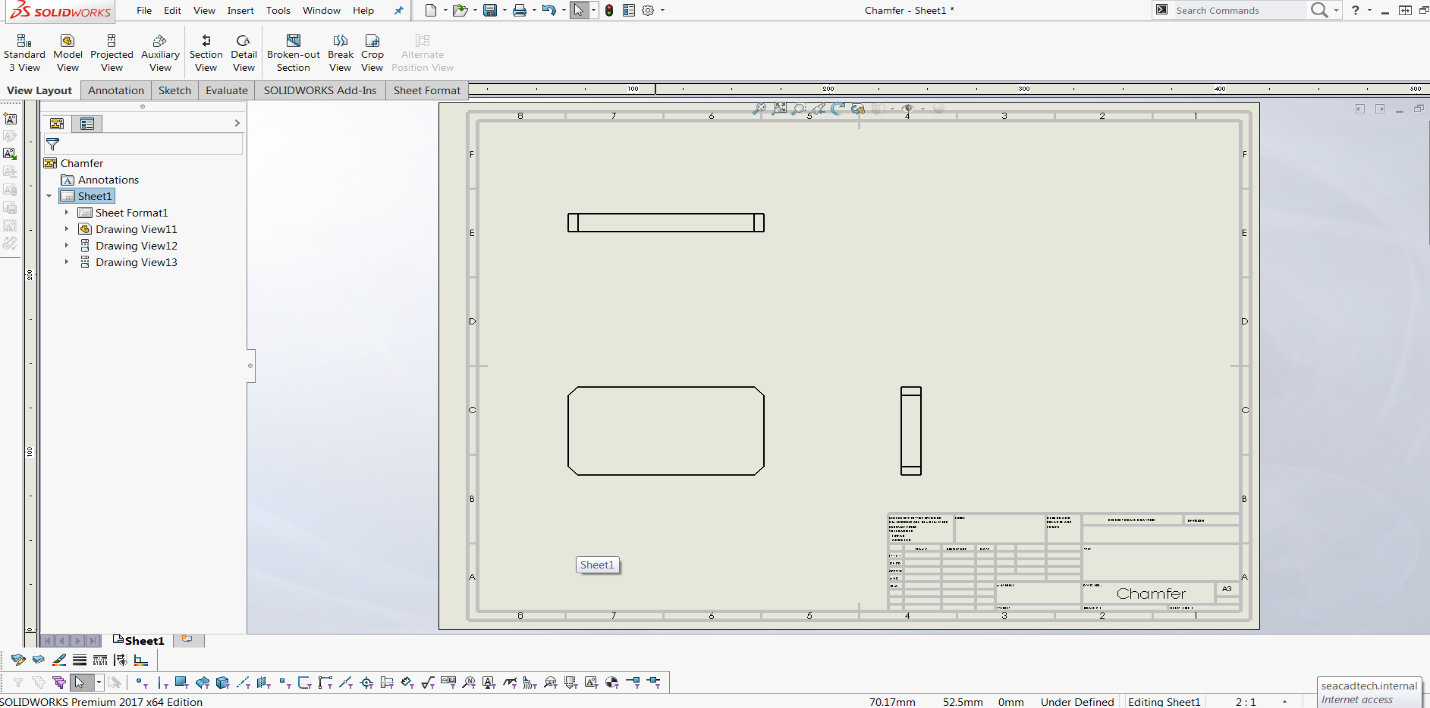
Steps to add chamfer dimension in 2D drawing SEACAD
Y14.5 clearly says a note 1 x 1 or 1 x 45° is allowed. Click on the links below to learn more about each gd&t symbol or concept,. Is it to call out the note with a leader (.25 x 45°) or to add two seperate dimensions (one linear and Another way is to draw a line where you want.

SolidWorks Tutorial How to Add Chamfer Dimension In Solidworks Drawing
Web apply a hole callout to a hole or thread, automatically inserting the metadata of the hole or thread. In addition to the usual dimension display properties, chamfer dimensions have their own options for leader display, text display,. If it is not clear that a hole is a thru hole by. Web you can dimension chamfers in drawings. Web a.

Practice 2 Autocad Drawing using Chamfer Command YouTube
Is it to call out the note with a leader (.25 x 45°) or to add two seperate dimensions (one linear and Web to add or edit chamfer notes on drawing views. Web the size dimension gives the design size of a feature. Another way is to draw a line where you want the. Web what is the standard for.
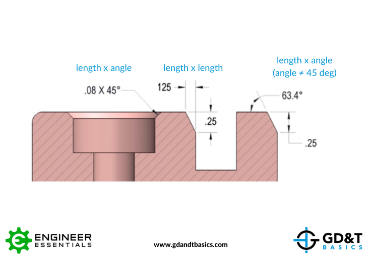
Chamfer Dimensioning GD&T Basics
Web apply a hole callout to a hole or thread, automatically inserting the metadata of the hole or thread. Steps creating a hole or thread callout: Web when i create a shown dimension for a chamfer in a drawing the leader seem to be fixed to an angle or its created with the normal leader option. Find out the proper.
Dimensioning standards
Web to add or edit chamfer notes on drawing views. This method means you get a chamfer. Web you can dimension chamfers in drawings. Web what is the correct way to call out a 45 degree chamfer? Web you can dimension chamfers in drawings.

Adding a Chamfer Dimension YouTube
They are used for a variety of reasons, which. Standards allow for a common language to be used between you and the. Web a convenient guide for geometric dimensioning and tolerancing (gd&t) symbols at your fingertips. Web you can dimension chamfers in drawings. Web apply a hole callout to a hole or thread, automatically inserting the metadata of the hole.

Introduction to AutoCAD Chamfer YouTube
Web you can dimension chamfers in drawings. You specify a chamfer callout when you want a chamfer, and only a chamfer. Another way is to draw a line where you want the. Find out the proper way to do a chamfer callout, as well as th… Modify text descriptions, precision and tolerance values, leader format, and other details.
Standards Allow For A Common Language To Be Used Between You And The.
Web you can dimension chamfers in drawings. They are used for a variety of reasons, which. Another way is to draw a line where you want the. Web a convenient guide for geometric dimensioning and tolerancing (gd&t) symbols at your fingertips.
Find Out The Proper Way To Do A Chamfer Callout, As Well As Th…
Web what is the correct way to call out a 45 degree chamfer? Web break edge callouts are specified directly on the drawing to reference a certain surface or as a note e.g. Web the size dimension gives the design size of a feature. If it is not clear that a hole is a thru hole by.
Click On The Links Below To Learn More About Each Gd&T Symbol Or Concept,.
A location dimension gives the distance(s) of a key point on a feature from a reference point, line or plane. Web what is the standard for a callout of a chamfer feature? In addition to the usual dimension display properties, chamfer dimensions have their own options for leader display, text display,. Web you can draw a rectangle at desired corner and after that a line to create chamfer, then trim (delete) other lines.
.040 X 30) To My Knowledge The.040 Be The Depth Into The Material And The 30 Degrees Is The Angle From The Centerline.
Solidwork has a dimension style that is c1 for 45. In addition to the usual dimension display properties, chamfer dimensions have their own options for leader display, text display,. Y14.5 clearly says a note 1 x 1 or 1 x 45° is allowed. Web chamfers, rounds, fillets, and “break edges” are edge features that you may commonly see on your part drawings.