Diameter Symbol In Engineering Drawing
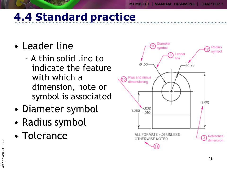
Diameter Symbol In Engineering Drawing - How to read symbols in an engineering drawing? Web a diameter symbol tells you that the zone for the geometric tolerance is cylindrical. Web basic types of symbols used in engineering drawings are countersink, counterbore, spotface, depth, radius, and diameter. This symbol is used to denote the diameter of a circle or cylindrical feature. In the example below, the drawing calls. How each type of hole is used in engineering. Web the counterbore dimension contains the counterbore symbol, the diameter of the counterbore, and the depth of the counterbore. Web it establishes symbols, rules, definitions, requirements, defaults, and recommended practices for stating and interpreting gd&t and related requirements for use on. Radius symbol — a symbol indicating that. By kelly curran glenn sokolowski.
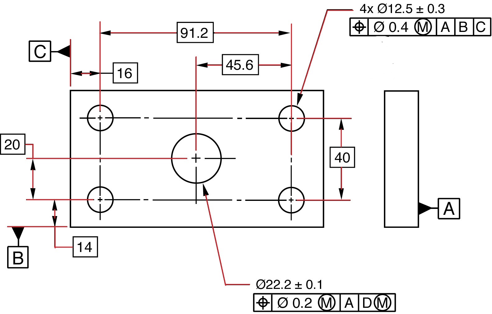
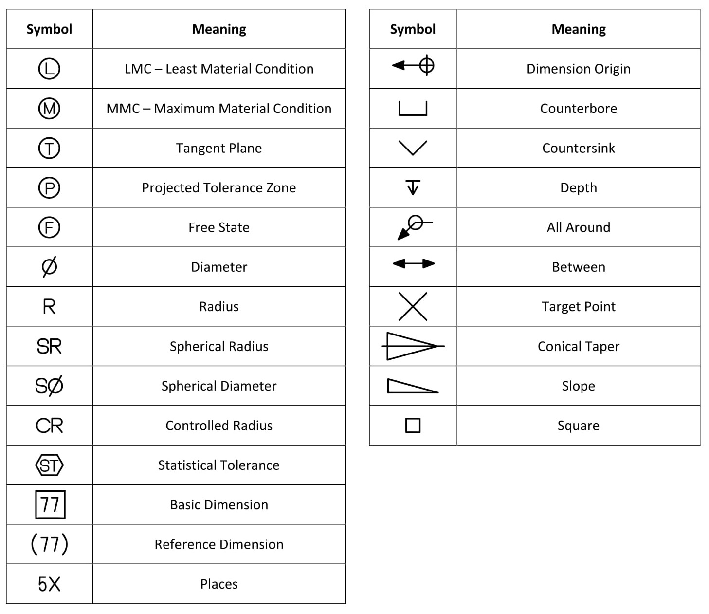
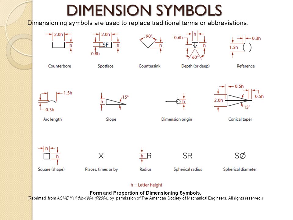
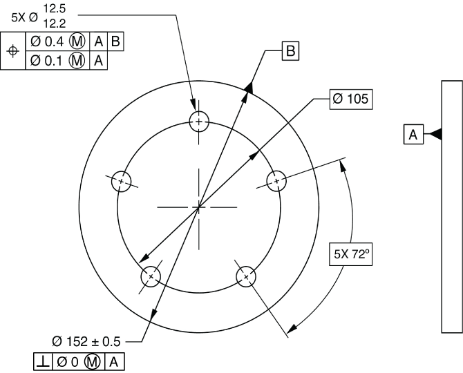
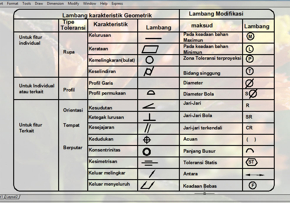
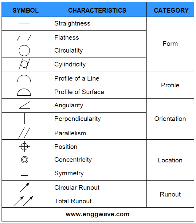
Web basic types of symbols used in engineering drawings are countersink, counterbore, spotface, depth, radius, and diameter. Web diameter symbol is the symbol which is placed preceding a numerical value indicating that the associated dimension shows the diameter of a circle. A convenient guide for geometric dimensioning and tolerancing (gd&t) symbols at your fingertips. Web symbols provide a “common language” for drafters all over the world. So if you want to learn the different types of. Web a diameter symbol tells you that the zone for the geometric tolerance is cylindrical. Web a diameter dimension is represented on a drawing with the ‘ø’ symbol preceding the value as shown in the below figure. 1) the diameter (and depth if blind) of the pilot hole drilled prior. Radius symbol — a symbol indicating that. Web the symbols used for each hole and how they are shown on engineering drawings.
A convenient guide for geometric dimensioning and tolerancing (gd&t) symbols at your fingertips. Web the purpose of this guide is to give you the basics of engineering sketching and drawing. This symbol is used to denote the diameter of a circle or cylindrical feature. How to read symbols in an engineering drawing? Web diameter symbol — a symbol indicating that the dimension shows the diameter of a circle. I've seen od/id used on rectangular tubes, so don't worry and use diameter symbol. So if you want to learn the different types of. Web symbols provide a “common language” for drafters all over the world. Indicates a circular feature when used on the field of a drawing or indicates that tolerance is diametrial when used in a feature control frame. By kelly curran glenn sokolowski.
Design Tech Academy (3) GD&T Symbols Diameter, Radius, Controlled
Web the note for a threaded hole is a specification of all information required for the creation of the hole. Web diameter symbol — a symbol indicating that the dimension shows the diameter of a circle. What kind of drawings do you create, so id can be mistaken with od? The symbol used is the greek. How each type of.
What Are Geometric Dimensioning And Tolerancing Gd T Symbols Vrogue
Circles on a drawing are dimensioned with a diameter. Web a diameter dimension is represented on a drawing with the ‘ø’ symbol preceding the value as shown in the below figure. Web basic types of symbols used in engineering drawings are countersink, counterbore, spotface, depth, radius, and diameter. In the example below, the drawing calls. What kind of drawings do.

GD&T 101 An Introduction to Geometric Dimensioning and Tolerancing
Web symbols provide a “common language” for drafters all over the world. The spherical diameter symbol indicates that. Web the purpose of this guide is to give you the basics of engineering sketching and drawing. What kind of drawings do you create, so id can be mistaken with od? A convenient guide for geometric dimensioning and tolerancing (gd&t) symbols at.
Dimension Symbols Of Drawing at GetDrawings Free download
In the example below, the drawing calls. What kind of drawings do you create, so id can be mistaken with od? Radius symbol (r or ⌀ with a diagonal line through it): We will treat “sketching” and “drawing” as one. Web the purpose of this guide is to give you the basics of engineering sketching and drawing.
Mechanical Drawing Dimension Symbols
Web a diameter symbol is used on the diameter dimension. Web the symbols used for each hole and how they are shown on engineering drawings. Web a diameter dimension is represented on a drawing with the ‘ø’ symbol preceding the value as shown in the below figure. The spherical diameter symbol indicates that. I've seen od/id used on rectangular tubes,.
Dimension Symbols Of Drawing at GetDrawings Free download
The symbol used is the greek letter phi ø. Web the purpose of this guide is to give you the basics of engineering sketching and drawing. Web the symbols used for each hole and how they are shown on engineering drawings. The spherical diameter symbol indicates that. This symbol is used to denote the diameter of a circle or cylindrical.
Diameter Symbol OER
I've seen od/id used on rectangular tubes, so don't worry and use diameter symbol. 1) the diameter (and depth if blind) of the pilot hole drilled prior. Web the spherical diameter symbol is a variant of the diameter symbol, with the letter “s” placed in front of the diameter symbol. How to read symbols in an engineering drawing? Web gd&t.
Dimension Symbols Of Drawing at GetDrawings Free download
By kelly curran glenn sokolowski. We will treat “sketching” and “drawing” as one. To specify a spherical zone, the symbol is the letter ‘s’ followed by the diameter symbol (⌀). However, symbols can be meaningful only if they are created according to the. Web a diameter symbol (⌀) signifies a diametric zone (cylindrical tolerance zone).

Lecture Notes Engineering Drawing Part 4
Web the counterbore dimension contains the counterbore symbol, the diameter of the counterbore, and the depth of the counterbore. The symbol used is the greek letter phi ø. When dimensioning a part with multiple concentric cylindrical features, you should stagger the dimension numbers so. Radius symbol (r or ⌀ with a diagonal line through it): A convenient guide for geometric.
GD&T Symbols GD&T Terms Geometric Dimensioning and »
By kelly curran glenn sokolowski. The symbol used is the greek. In the example below, the drawing calls. However, symbols can be meaningful only if they are created according to the. Web the spherical diameter symbol is a variant of the diameter symbol, with the letter “s” placed in front of the diameter symbol.
Web The Counterbore Dimension Contains The Counterbore Symbol, The Diameter Of The Counterbore, And The Depth Of The Counterbore.
Web the spherical diameter symbol is a variant of the diameter symbol, with the letter “s” placed in front of the diameter symbol. Web the note for a threaded hole is a specification of all information required for the creation of the hole. Web it establishes symbols, rules, definitions, requirements, defaults, and recommended practices for stating and interpreting gd&t and related requirements for use on. 1) the diameter (and depth if blind) of the pilot hole drilled prior.
So If You Want To Learn The Different Types Of.
Why abbreviations and symbols are needed for engineering drawing? Web the symbols used for each hole and how they are shown on engineering drawings. By kelly curran glenn sokolowski. To specify a spherical zone, the symbol is the letter ‘s’ followed by the diameter symbol (⌀).
This Symbol Is Used To Denote The Diameter Of A Circle Or Cylindrical Feature.
Web diameter symbol is the symbol which is placed preceding a numerical value indicating that the associated dimension shows the diameter of a circle. Web gd&t symbols | gd&t basics. Web diameter symbol — a symbol indicating that the dimension shows the diameter of a circle. How to read symbols in an engineering drawing?
Radius Symbol — A Symbol Indicating That.
The spherical diameter symbol indicates that. Web a diameter dimension is represented on a drawing with the ‘ø’ symbol preceding the value as shown in the below figure. When dimensioning a part with multiple concentric cylindrical features, you should stagger the dimension numbers so. Web basic types of symbols used in engineering drawings are countersink, counterbore, spotface, depth, radius, and diameter.