Dimensioning Rules In Engineering Drawing
Dimensioning Rules In Engineering Drawing - Learn the fundamental rules of dimensioning in engineering/architectural/structural drawings. Web for most of the architectural drawing best practices, the source is national cad standards (ncs, usa). The dimensions in the part drawing shall be marked in accordance with the standard, complete, clear and reasonable. Dimensions should be placed in the view which most clearly describes the feature being dimensioned. The dimensions are 3” long, 2 1/8” wide, 1 5/8” high with a 45 angle ½” deep. Do not leave any size, shape, or material in doubt. Web sometime space and time is limited and you might have to bend the typical rules of drawing and dimensioning. Property indicators (symbols) rules for dimensioning. Before an object can be built, complete information about both the size and shape of the object must be available. To avoid confusion and the possibility of error, no dimension should be repeated twice on any sketch or drawing.
Dimensions should be placed in the view which most clearly describes the feature being dimensioned. Each dimension should be given clearly so it can be interpreted in only one way. Web every dimension must have an associated tolerance, and that tolerance must be clearly shown on the drawing. Web this document discusses dimensioning practices for engineering drawings. Dimensions must be placed in appropriate positions. Web it establishes symbols, rules, definitions, requirements, defaults, and recommended practices for stating and interpreting gd&t and related requirements for use on engineering drawings, models defined in digital data files, and in related documents. Note the figures in this part of iso 129 merely illustrate the text and are not intended to reflect actual usage. The rules that are relevant to interpreting basic to intermediate engineering drawing dimensions are explained. Dimension elements dimensioning a drawing also identifies the tolerance (or accuracy) required for each dimension. Learn the fundamental rules of dimensioning in engineering/architectural/structural drawings.
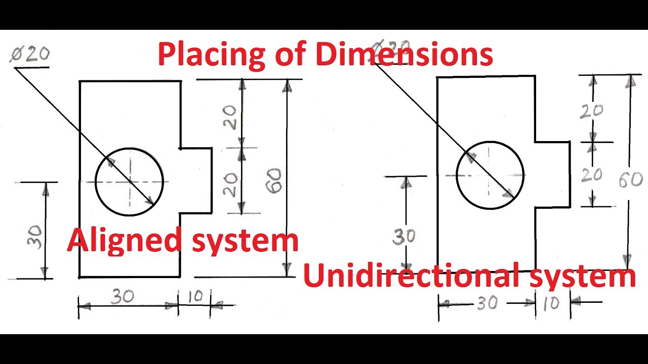
Web it establishes symbols, rules, definitions, requirements, defaults, and recommended practices for stating and interpreting gd&t and related requirements for use on engineering drawings, models defined in digital data files, and in related documents. Web sometime space and time is limited and you might have to bend the typical rules of drawing and dimensioning. Web the general guideline is that each dimension should be placed on the view which shows the dimensioned feature most clearly, and which gives the clearest and least cluttered drawing. Using gd&t results in a more accurate design, larger tolerances for less important design features, and cost savings for manufacturing. Rule 1) dimensions should be arranged for maximum readability. Note the figures in this part of iso 129 merely illustrate the text and are not intended to reflect actual usage. Dimension elements dimensioning a drawing also identifies the tolerance (or accuracy) required for each dimension. Although there are tens of hundreds of guidelines for dimensioning drawings properly, in this article, i have selected only some of the most popular ones that frequently appear in a drawing. Web dimensioning of part drawings. Web units of dimensions.

Rules For Dimensioning Mechanical Drawings Rules, Mechanic, Autocad
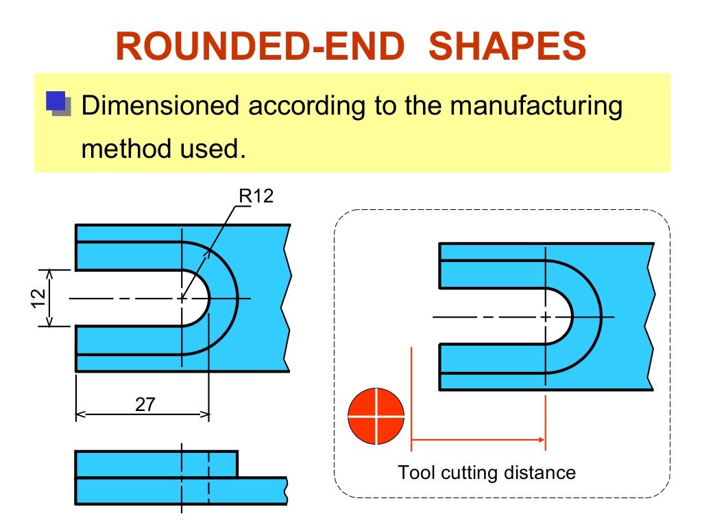
Web dimensioning of part drawings. Web every dimension must have an associated tolerance, and that tolerance must be clearly shown on the drawing. Methods and steps for dimensioning parts. The dimensions are 3” long, 2 1/8” wide, 1 5/8” high with a 45 angle ½” deep. 12k views 2 years ago #howtodraw #geometry.
Technical Drawing Dimensions Design Talk
Dimensioning should follow these guidelines. Dimensions should be placed in the view which most clearly describes the feature being dimensioned. Dimensions should not be duplicated or the same information given in two different ways (dual dimensioning excluded). Although there are tens of hundreds of guidelines for dimensioning drawings properly, in this article, i have selected only some of the most.

Rules For Dimensioning Mechanical Drawings YouTube
Correct values must be given. Double dimensioning of a feature is not permitted. The dimensions are 3” long, 2 1/8” wide, 1 5/8” high with a 45 angle ½” deep. Although there are tens of hundreds of guidelines for dimensioning drawings properly, in this article, i have selected only some of the most popular ones that frequently appear in a.
Dimensioning rules in engineering drawing
It includes projection line, leader line, termination of the dimension line, the origin indication, symbols and the dimension itself. Web rules of dimensioning in engineering drawing. The dimensions are 3” long, 2 1/8” wide, 1 5/8” high with a 45 angle ½” deep. Methods and steps for dimensioning parts. Screw thread representation (iaw ansi y14.6 and y14.6am) 13.

Dimensioning How To Clearly Communicate The Sizes Shapes Locations And
The rules that are relevant to interpreting basic to intermediate engineering drawing dimensions are explained. Dimensions and notations must be placed on the sketch where they can be clearly and easily read. Dimensions should be placed in the view which most clearly describes the feature being dimensioned. Screw thread representation (iaw ansi y14.6 and y14.6am) 13. Web this document discusses.
CivilSeek Everything you need to know about Civil Engineering.
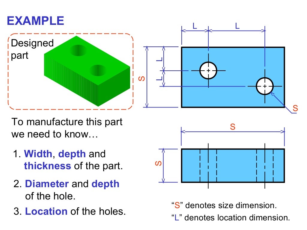
Web geometric dimensioning and tolerancing is a set of rules and gd&t symbols used on a drawing to communicate the intent of a design, focusing on the function of the part. Basic requirements for dimensioning in part drawings. Web rules of dimensioning in engineering drawing. To avoid confusion and the possibility of error, no dimension should be repeated twice on.
Dimensioning rules in engineering drawing
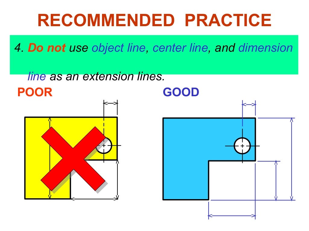
The most important thing is to keep the drawing clean, concise, try to not a repeat dimensions but give all required ones. It then covers components of dimensioning like extension lines, dimension lines, leader lines and. For example, the american society of mechanical engineers (asme) has developed a set of guidelines that outline the proper. Web rules of dimensioning in.
Dimensioning rules in engineering drawing
Web this document discusses dimensioning practices for engineering drawings. On a multiview drawing, dimensions should generally be. Dimension elements dimensioning a drawing also identifies the tolerance (or accuracy) required for each dimension. A complete set of dimensions will permit only one interpretation needed to construct the part. Gears (iaw ansi y14.7.1 and.
Rules Drawing at GetDrawings Free download
Web engineering drawing practices ” types and application of engineering drawings. Web sometime space and time is limited and you might have to bend the typical rules of drawing and dimensioning. Before an object can be built, complete information about both the size and shape of the object must be available. Dimensions should not be duplicated or the same information.

GENERAL RULES OF DIMENSIONING in Engineering Drawing YouTube
Web three principles of dimensioning must be followed: Using gd&t results in a more accurate design, larger tolerances for less important design features, and cost savings for manufacturing. Web the general guideline is that each dimension should be placed on the view which shows the dimensioned feature most clearly, and which gives the clearest and least cluttered drawing. Screw thread.
Web Three Principles Of Dimensioning Must Be Followed:
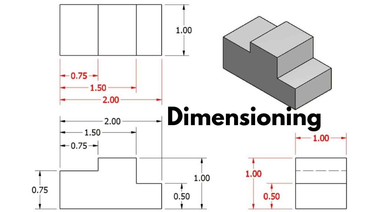
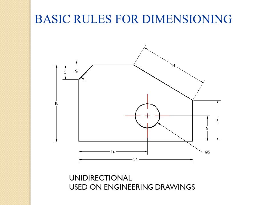
For example, the american society of mechanical engineers (asme) has developed a set of guidelines that outline the proper. On a multiview drawing, dimensions should generally be. Web dimensioning practice once the shape of a part is defined with an orthographic drawing (i.e., in projections), the size information is added in the form of dimensions. It includes projection line, leader line, termination of the dimension line, the origin indication, symbols and the dimension itself.
Web Dimensioning Of Part Drawings.
Dimensioning should follow these guidelines. Screw thread representation (iaw ansi y14.6 and y14.6am) 13. Each dimension should be given clearly so it can be interpreted in only one way. Do not leave any size, shape, or material in doubt.
The Exact Shape Of The Part Or Assembly Is Shown By The Different Views In The Drawing Sheet.
Dimensioning and tolerancing (iaw asme y14.5m) 11. Surface texture (iaw asme b46.1 and asme y14.36m) 12. Property indicators (symbols) rules for dimensioning. Web for most of the architectural drawing best practices, the source is national cad standards (ncs, usa).
Dimensions Should Not Be Duplicated Or The Same Information Given In Two Different Ways (Dual Dimensioning Excluded).
Using gd&t results in a more accurate design, larger tolerances for less important design features, and cost savings for manufacturing. A complete set of dimensions will permit only one interpretation needed to construct the part. The rules that are relevant to interpreting basic to intermediate engineering drawing dimensions are explained. Web it establishes symbols, rules, definitions, requirements, defaults, and recommended practices for stating and interpreting gd&t and related requirements for use on engineering drawings, models defined in digital data files, and in related documents.