Draw Ammeter
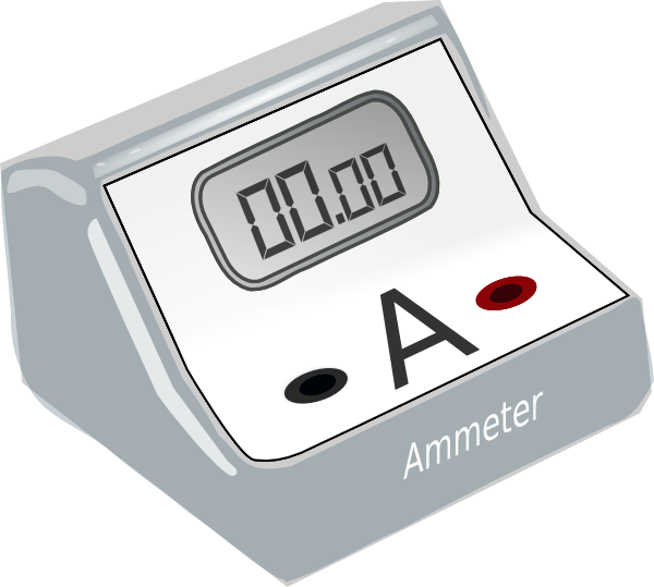
Draw Ammeter - To measure electric current in a circuit, ammeter must be connected in series because, in series connection, ammeter experiences the same amount of current that flows in the circuit. It has some amount of internal resistance. Web about press copyright contact us creators advertise developers terms privacy policy & safety how youtube works test new features nfl sunday ticket press copyright. Saturday 4 may 2024 • 9:00am. The ammeter is a measuring instrument used to find the strength of current flowing around an electrical circuit when connected in series with the part of the circuit being measured. Web learn how to measure voltage and current in electrical circuits using voltmeters and ammeters. Web ammeter measures the electric current in the circuit. By the end of this section, you will be able to: The ammeter reads 5a, therefore the current through the bulb is 5a. Find the resistance that must be placed in series with a galvanometer to allow it.
Web current is the measure of the flow of electricity through a circuit in amperes (amps) by a device known as an ammeter. In this explainer, we will learn how to describe the combination of a galvanometer with a shunt resistor to design a dc ammeter. Instrument used to measure electric potential difference. Null measurements balance voltages, so there is no current flowing through the measuring device and the circuit is unaltered. Describe how a galvanometer can be used as either a voltmeter or an ammeter. Explain why a voltmeter must be connected in parallel with the circuit. The ammeter would have the same reading if located between points d and e or between points f and a as it does in the position shown. By the end of this section, you will be able to: To measure electric current in a circuit, ammeter must be connected in series because, in series connection, ammeter experiences the same amount of current that flows in the circuit. Describe how a galvanometer can be used as either a voltmeter or an ammeter.
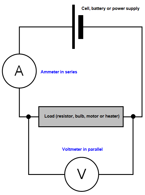
Web instead of drawing an arrow to indicate current, we can instead draw an ammeter at that point. Web learn how to measure voltage and current in electrical circuits using voltmeters and ammeters. The three “donut” current transformers (ct’s) can be seen in the rear of the panel. This is because we want to. Explain why a voltmeter must be connected in parallel with the circuit. It has some amount of internal resistance. Web about press copyright contact us creators advertise developers terms privacy policy & safety how youtube works test new features nfl sunday ticket press copyright. An ammeter is a device that can be used to measure the current in a circuit. Discover why voltmeters are connected in parallel and ammeters in series. Draw a diagram showing an ammeter correctly connected in a circuit.

How is an ammeter connected in a circuit how is a voltmeter connected
Web instead of drawing an arrow to indicate current, we can instead draw an ammeter at that point. Why does an ammeter need to be in series? The internal resistance of this device is ‘0’ however in practical; The name is derived from the si unit of electric current, ampere. Describe how a galvanometer can be used as either a.

Digital Ammeter Circuit Diagram
Web learn for free about math, art, computer programming, economics, physics, chemistry, biology, medicine, finance, history, and more. The internal resistance of this device is ‘0’ however in practical; Draw a diagram showing an ammeter correctly connected in a circuit. Home inspection standards for electrical inspections do not require the inspector to insert any instrument into the service panel. Web.
.png)
Correct Way To Connect Ammeter And Voltmeter Seeds Wiring
By the end of this section, you will be able to: All of the current in this circuit flows through the meter. The three “donut” current transformers (ct’s) can be seen in the rear of the panel. In this explainer, we will learn how to describe the combination of a galvanometer with a shunt resistor to design a dc ammeter..

An isolated ammeter Royalty Free Vector Image VectorStock
This is because we want to. Understand the importance of resistance in these devices to ensure accurate readings and prevent damage. Explain why a voltmeter must be connected in parallel with the circuit. Instrument used to measure current. It has some amount of internal resistance.

What is an ammeter and where and how it is used
The ammeter reads 5a, therefore the current through the bulb is 5a. Web learn for free about math, art, computer programming, economics, physics, chemistry, biology, medicine, finance, history, and more. Web standard measurements of voltage and current alter circuits, introducing numerical uncertainties. The three “donut” current transformers (ct’s) can be seen in the rear of the panel. Web about press.

Ammeter Royalty Free Vector Image VectorStock
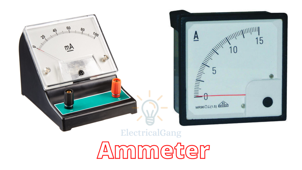
The three “donut” current transformers (ct’s) can be seen in the rear of the panel. An ammeter is connected in series with a bulb. Instrument used to measure current. By the end of this section, you will be able to: The ammeter would have the same reading if located between points d and e or between points f and a.

Ammeter Definition, Function, How It Works Matob
The ammeter is a measuring instrument used to find the strength of current flowing around an electrical circuit when connected in series with the part of the circuit being measured. Describe how a galvanometer can be used as either a voltmeter or an ammeter. By the end of this section, you will be able to: Explain why a voltmeter must.
Ammeter Clip Art at vector clip art online, royalty free
Draw a diagram showing an ammeter correctly connected in a circuit. Instrument used to measure current. Home inspection standards for electrical inspections do not require the inspector to insert any instrument into the service panel. Web learn how to measure voltage and current in electrical circuits using voltmeters and ammeters. This is because we want to.
What is an Ammeter,Types and it's Working Principle ? Marinerspoint Pro
Web instead of drawing an arrow to indicate current, we can instead draw an ammeter at that point. Find the resistance that must be placed in series with a galvanometer to allow it. Web a meter designed to measure electrical current is popularly called an “ammeter” because the unit of measurement is “amps.” in ammeter designs, external resistors added to.
Working Principle of Ammeter Complete Guide (2023)
Voltmeters draw some extra current, whereas ammeters reduce current flow. Web a meter designed to measure electrical current is popularly called an “ammeter” because the unit of measurement is “amps.” in ammeter designs, external resistors added to extend the usable range of the movement are connected in parallel with the movement rather than in series as is the case for.
Instrument Used To Measure Current.
Also, draw a schematic diagram of this same circuit (with the ammeter connected). Web an ammeter (a) is placed in series to measure current. Voltmeters draw some extra current, whereas ammeters reduce current flow. By the end of this section, you will be able to:
Find The Resistance That Must Be Placed In Series With A Galvanometer To Allow It.
Understand the importance of resistance in these devices to ensure accurate readings and prevent damage. Web current is the measure of the flow of electricity through a circuit in amperes (amps) by a device known as an ammeter. Describe how a galvanometer can be used as either a voltmeter or an ammeter. Saturday 4 may 2024 • 9:00am.
So This Device Measures The Current Flow In Ampere Is Named As An Ammeter Or Ampere Meter.
Explain why a voltmeter must be connected in parallel with the circuit. The ammeter reads 5a, therefore the current through the bulb is 5a. Web instead of drawing an arrow to indicate current, we can instead draw an ammeter at that point. Web ammeter measures the electric current in the circuit.
Describe How A Galvanometer Can Be Used As Either A Voltmeter Or An Ammeter.
Draw a diagram showing an ammeter correctly connected in a circuit. The name is derived from the si unit of electric current, ampere. Web standard measurements of voltage and current alter circuits, introducing numerical uncertainties. Draw a diagram showing an ammeter correctly connected in a circuit.