Draw Lens
Draw Lens - Complete the ray diagram by drawing where the image of this object will be seen. Simulation of image formation in concave and convex lenses. Ray tracing is limited by the accuracy with which you can draw, but it is highly useful both conceptually and visually. Web an object is placed outside the focal point of a concave lens. Web lenses serve to refract light at each boundary. To find the power of the lens, we must first convert the focal length to meters; Because of the special geometric shape of a lens, the light rays are. Where both rays meet is point a'. Move the tip of the object arrow to move the object. The function of adding various diagrams into the chart or graph takes this template well outstand the.
This video breaks down how convex lenses form images. (25.6.2) (25.6.2) f = 8.00 c m. The dashed lines are not rays; So, it passes through focus after refraction. By manipulating the object and lens locations, you can create real or virtual images. Focal length, object distance, and image distance. It emphasizes how to determine whether these values are positive or negative based on the lens type (converging or diverging) and their positions. Draw a line from the top of the object through the middle of the lens. Move the tip of the object arrow to move the object. The symbol ↕ used to draw the ray diagrams indicates.
Web ray diagrams for lenses. The image formed by a single lens can be located and sized with three principal rays. The focal length, ƒ, of a diverging lens is negative.an expanded view of the path taken by ray 1 shows the perpendiculars and the. It emphasizes how to determine whether these values are positive or negative based on the lens type (converging or diverging) and their positions. To find the power of the lens, we must first convert the focal length to meters; Place arrowheads upon the rays to indicate their direction of travel. Because of the special geometric shape of a lens, the light rays are. So, the ray will go through without any deviation. By manipulating the object and lens locations, you can create real or virtual images. Web an increase in magnetic flux through a coil of 100 turns in 0.1 s is 0.001 wb.
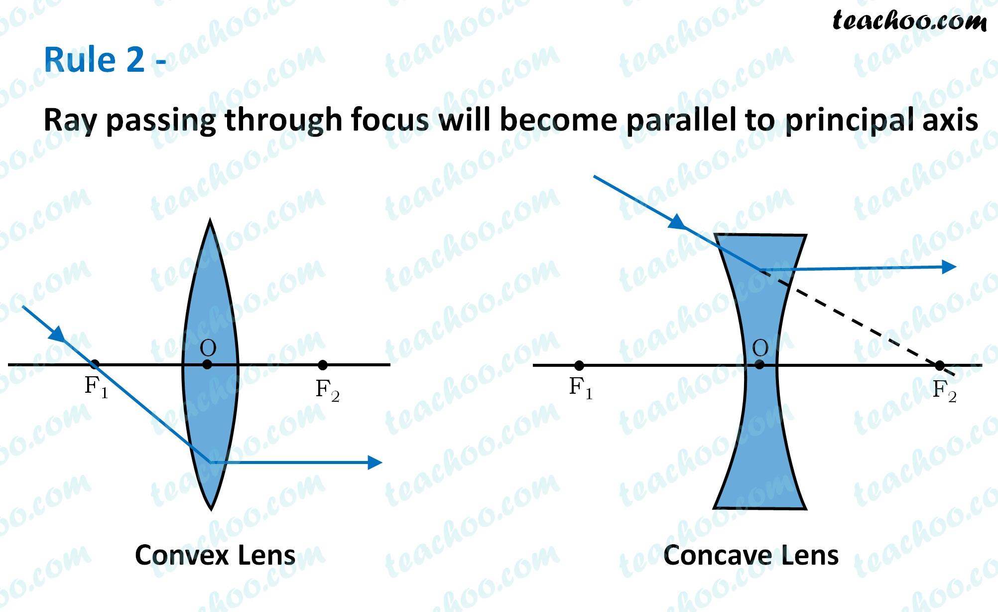
Rules for drawing Ray Diagram in Convex and Concave Lens Teachoo
The thin lens equations give the most precise results, being limited only by the accuracy of the given information. And as the same ray of light exits the lens, it is refracted again. Click here to donate to ophysics.com to help keep the site going. Because of the special geometric shape of a lens, the light rays are. Once these.

How to draw lens for ray diagrams? YouTube
Web ray tracing and the use of the thin lens equations produce consistent results. The function of adding various diagrams into the chart or graph takes this template well outstand the. Web this demonstration lets you visualize the ray diagrams for converging and diverging lenses. Once these incident rays strike the lens, refract them according to the three rules of.

Convex and concave lens, vector illustration diagrams VectorMine
The net effect of the refraction of light at these two boundaries is that the light ray has changed directions. Draw the third ray to the exact center of the lens. As a ray of light enters a lens, it is refracted; Once these incident rays strike the lens, refract them according to the three rules of refraction for double.
Lens Drawing at GetDrawings Free download
And as the same ray of light exits the lens, it is refracted again. Web this demonstration lets you visualize the ray diagrams for converging and diverging lenses. You don't need to be a good artist to learn them. Once these incident rays strike the lens, refract them according to the three rules of refraction for converging lenses. It explores.
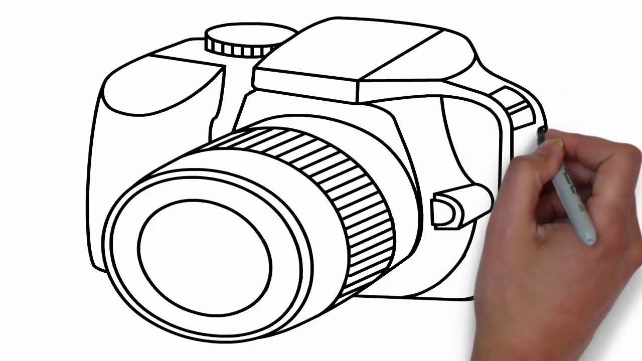
How to draw a Camera Easy step by step drawing DSLR YouTube
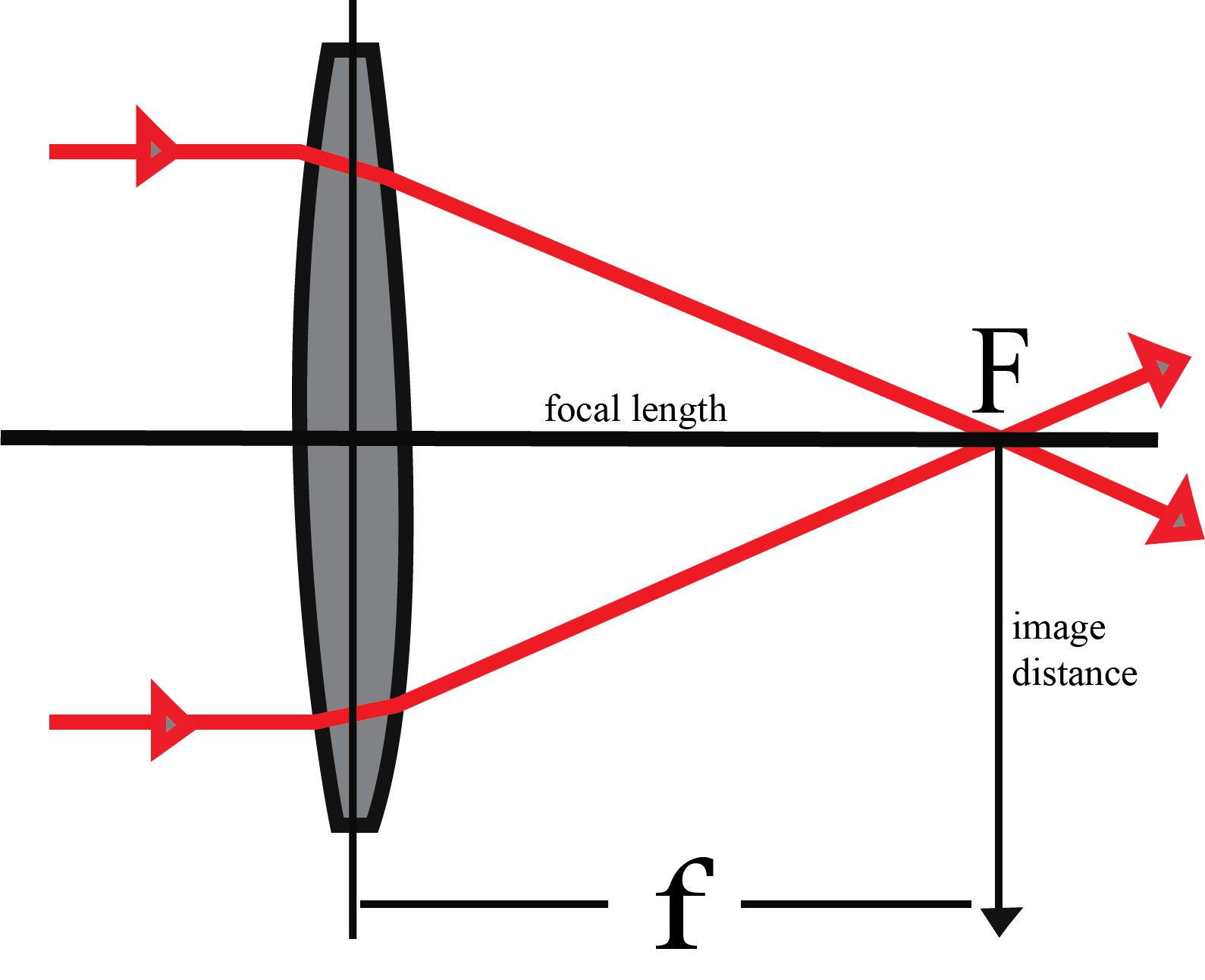
When an object is placed at infinity, the real image is formed at the focus. We draw another ray which passes through optical center. You don't need to be a good artist to learn them. As a ray of light enters a lens, it is refracted; Move the point named focus' to the right side of the lens to change.

Rules for drawing Ray Diagram in Convex and Concave Lens Teachoo
The maximum induced emf generated in the coil is. The video also introduces the idea of a lens's focal point and the thin lens assumption. The video emphasizes understanding the process rather than memorizing. Simulation of image formation in concave and convex lenses. By manipulating the object and lens locations, you can create real or virtual images.
How To Draw A Ray Diagram For A Convex Lens
Only drag them into the view and start your work. The image formed by a single lens can be located and sized with three principal rays. The dashed lines are not rays; Move the point named focus' to the right side of the lens to change to a concave lens. The ray that passes through the focal point on the.
Camera Lens Drawing at Explore collection of
When an object is placed at infinity, the real image is formed at the focus. Web the focal length of the lens is the distance from the center of the lens to the spot, given to be 8.00 cm. How does a lens or mirror form an image? This image is formed between f 2 and 2f 2. Observe how.
Lens Drawing at Explore collection of Lens Drawing
Draw the third ray to the exact center of the lens. This video explores the concept of convex lenses, focusing on how they refract and transmit light. Shows the effect of a concave lens on rays of light entering it parallel to its axis (the path taken by ray 2 in the figure is the axis of the lens). Web.

How To Draw Camera Lens at How To Draw
Web ray diagrams for lenses. Only drag them into the view and start your work. Move the point named focus' to the right side of the lens to change to a concave lens. It explores different scenarios where an object is placed at various distances from the lens. See how light rays are refracted by a lens or reflected by.
The Maximum Induced Emf Generated In The Coil Is.
Web this video explains the thin lens formula and its components: The image size will not be the same as the object. Only drag them into the view and start your work. Draw the object relative to the lens and label the focal length on either.
When An Object Is Placed Beyond The Centre Of Curvature, The Real Image Is Formed Between The Centre Of Curvature And Focus.
Place arrowheads upon the rays to indicate their direction of travel. The dashed lines are not rays; Where both rays meet is point a'. And as the same ray of light exits the lens, it is refracted again.
How Does A Lens Or Mirror Form An Image?
The net effect of the refraction of light at these two boundaries is that the light ray has changed directions. The instructor demonstrates how rays refract through the lens, forming real, inverted, or virtual images. The image formed by a single lens can be located and sized with three principal rays. Shows the effect of a concave lens on rays of light entering it parallel to its axis (the path taken by ray 2 in the figure is the axis of the lens).
Observe How The Image Changes When You Adjust The Focal Length Of The Lens, Move The Object, Or Move The Screen.
By manipulating the object and lens locations, you can create real or virtual images. The video also introduces the magnification formula for determining image height. Complete the ray diagram by drawing where the image of this object will be seen. We draw another ray which passes through optical center.