Draw Shear And Moment Diagrams For The Beam
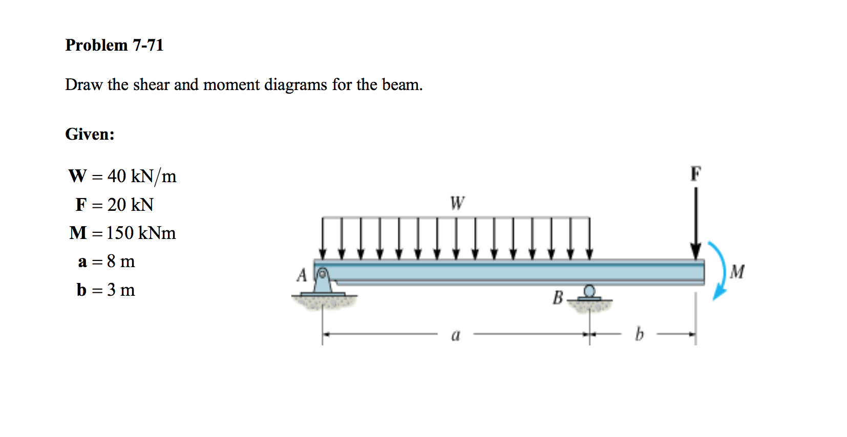
Draw Shear And Moment Diagrams For The Beam - 20 kn 40 kn/m cl 150 kn m 8 m 3 m prob. Establish the m and x axes and plot the values of the moment at the ends of the beam. Taking moment about point b , we get. Determine new origin (x n) and use positive sign conventions to. M = f_c\times z = f_t\times z \tag {2} m = f c ×z =f t ×z (2) 💡 the internal bending moment m m, is the bending moment we represent in a bending moment diagram. Web this is an example problem that will show you how to graphically draw a shear and moment diagram for a beam. (a)upward acting forces give rise to positive changes in v(x). Web steps to construct shear force and bending moment diagrams. Over whole beam, 0 x l place section at x. Draw the shear and moment diagrams for the beam.
In a simply supported beam, the only vertical force is the 5kn/m. The following examples show the shear and moment diagrams for each beam. Wall reactions for the cantilevered beam. According the sign convention on the previous page: [latex]\delta m=\int v (x)dx [/latex] (equation 6.2) equation 6.2 states that the change in moment equals the area under the shear diagram. There are 4 steps to solve this one. Web plots of v(x) and m(x) are known as shear and bending moment diagrams, and it is necessary to obtain them before the stresses can be determined. Draw the shear and moment diagrams for the beam. Using the machine in figure 1, we will measure the shear force and bending moment of a beam after subjecting it to given loads. Experts have been vetted by chegg as specialists in this subject.
Web shear and moment diagrams are graphs which show the internal shear and bending moment plotted along the length of the beam. Draw the shear and moment diagrams for the beam. Web steps to construct shear force and bending moment diagrams. According the sign convention on the previous page: Draw the shear and moment diagrams for the beam. Draw the shear and moment diagrams for the beam, and determine the shear and moment in the beam as functions of x for 0 x 4 ft, 4 ft x 10 ft, and 10 ft x 14 ft 250 lb 250 lb 150 lb/ft 6 ft 4 ft 4 ft prob. We go through breaking a beam into segments, and then we learn about the relatio. (see above) sum up the forces in the vertical direction. Shear and moment diagrams the beam is. Web this video explains how to draw shear force diagram and bending moment diagram with easy steps for a simply supported beam loaded with a concentrated load.

Shear force and bending moment diagrams for beams pdf
You'll get a detailed solution from a subject matter expert that helps you learn core concepts. Taking moment about point b , we get. Using the machine in figure 1, we will measure the shear force and bending moment of a beam after subjecting it to given loads. Web separated by a distance or lever arm, z. [latex]\delta m=\int v.

Learn How To Draw Shear Force And Bending Moment Diagrams Engineering
Wall reactions for the cantilevered beam. 200 lb ft b x 4 ft 4 ft 150 lb/ft 6 ft 200 lb ft a. Over whole beam, 0 x l place section at x. Equation 6.1 suggests the following expression: Draw the shear and moment diagrams for the beam, and determine the shear and moment in the beam as functions of.

Learn How To Draw Shear Force And Bending Moment Diagrams Engineering
Draw the shear and moment diagrams for the beam. 20 kn 40 kn/m cl 150 kn m 8 m 3 m prob. Over whole beam, 0 x l place section at x. Taking moment about point b , we get. Using the machine in figure 1, we will measure the shear force and bending moment of a beam after subjecting.

Shear and moment diagrams geekloki
Introduction notations relative to “shear and moment diagrams” e = modulus of elasticity, psi i = moment of inertia, in.4 l = span length of the bending. Cut beam to reveal internal forces and moments* ; Wall reactions for the cantilevered beam. Shear and moment diagrams the beam is. Since beams primarily support vertical loads the axial.
Solved Draw the shear and moment diagrams for the beam.
(a)upward acting forces give rise to positive changes in v(x). Draw a free body diagram of the beam with global coordinates (x); Web shear and moment diagrams. We go through breaking a beam into segments, and then we learn about the relatio. M = f_c\times z = f_t\times z \tag {2} m = f c ×z =f t ×z (2).

Solved Draw the shear and moment diagrams for the beam, and
[latex]\delta m=\int v (x)dx [/latex] (equation 6.2) equation 6.2 states that the change in moment equals the area under the shear diagram. Wall reactions for the cantilevered beam. In general the process goes like this:1) calcul. You'll get a detailed solution from a subject matter expert that helps you learn core concepts. Calculate the reaction forces using equilibrium equations (.

Solved Draw the shear and moment diagrams for the beam
2.draw the entire beam showing all loads and reactions. In this experiment, we will work on drawing the shear and bending diagram of a beam. Web egr2312 lab experiment n°8 shearing and bending moment diagrams 1. Web shear and moment diagrams and formulas are excerpted from the western woods use book, 4th edition, and are provided herein as a courtesy.

Drawing Shear and Moment Diagrams for Beam YouTube
There are 4 steps to solve this one. Web learn to draw shear force and moment diagrams using 2 methods, step by step. The bending moment diagram shows how m m (and. Assume that the beam is cut at point c a distance of x from he left support and the portion of the beam to the right of c.

Draw the shear and moment diagrams for the beam.
Experts have been vetted by chegg as specialists in this subject. 2.draw the entire beam showing all loads and reactions. Web lined up below the shear diagram, draw a set of axes. Web this is an example problem that will show you how to graphically draw a shear and moment diagram for a beam. Web 2) calculate the shear force.

Solved Draw the shear and moment diagrams for the beam.
For details on how to solve each, go to: In this experiment, we will work on drawing the shear and bending diagram of a beam. Over whole beam, 0 x l place section at x. Also draw shear force diagram (sfd) and bending moment diagram (bmd). Assume that the beam is cut at point c a distance of x from.
Consider A Simple Beam Shown Of Length L That Carries A Uniform Load Of W (N/M) Throughout Its Length And Is Held In Equilibrium By Reactions R 1 And R 2.
Web beamguru.com is a online calculator that generates bending moment diagrams (bmd) and shear force diagrams (sfd), axial force diagrams (afd) for any statically determinate (most simply supported and cantilever beams) and statically indeterminate beams, frames and trusses.the calculator is fully customisable to suit most beams,. Web egr2312 lab experiment n°8 shearing and bending moment diagrams 1. We go through breaking a beam into segments, and then we learn about the relatio. Draw the shear and moment diagrams for the beam.
Web 2 Shear And Bending Moment Diagrams 1.Determine All The Reactions On The Beam.
Calculate the reaction forces using equilibrium equations ( ∑ forces = 0 and ∑ moments = 0 ); [latex]\delta m=\int v (x)dx [/latex] (equation 6.2) equation 6.2 states that the change in moment equals the area under the shear diagram. There are 4 steps to solve this one. Over whole beam, 0 x l place section at x.
They Allow Us To See Where The Maximum Loads Occur So That We Can Optimize The Design To Prevent Failures And Reduce The Overall Weight And Cost Of The Structure.
For details on how to solve each, go to: You might recognise this pair of forces as forming a couple or moment m m. Web this problem has been solved! Establish the m and x axes and plot the values of the moment at the ends of the beam.
The Bending Moment Diagram Shows How M M (And.
M = f_c\times z = f_t\times z \tag {2} m = f c ×z =f t ×z (2) 💡 the internal bending moment m m, is the bending moment we represent in a bending moment diagram. (see above) sum up the forces in the vertical direction. Using the machine in figure 1, we will measure the shear force and bending moment of a beam after subjecting it to given loads. Shear force and bending moment diagrams are analytical tools used in conjunction with structural analysis to help perform structural design by determining the value of shear forces and bending moments at a given point of a structural element.