Draw The Logic Circuit
Draw The Logic Circuit - Open the logic gate shape library to draw the diagram by dragging and dropping the components on to the canvas. Web on the circuit diagram, add temporary letters after each gate (c, d, e in the above example) create a blank truth table, allowing space for all the temporary letters (stages) write into the truth table all the possible unique input combinations (a and b combinations in this example) in the truth table, calculate the output at each temporary. Web visual paradigm's logic diagram tool features a handy diagram editor that allows you to draw logic diagrams swiftly. Detailed steps, logic circuits, kmap, truth table, & quizes. You can see an example of each logic gate here. Use our logic gates diagram tool to create the diagrams as follow: Web build and simulate circuits right in your browser. A signal to run the motor (m). Design circuits online in your browser or using the desktop application. Computers use logic gates to transform the 1s and 0s from input wires.
=1 & start building now. Design circuits online in your browser or using the desktop application. Work with a team on a single synchronized circuit. Simulator.io is an online cad tool for logic circuits. The safety button must be pressed (and maintained) before the start / stop button is pushed to start the mot Intuitive graphical user interface, allows you to create unrestricted circuit hierarchy with multi bit buses, debug circuits behavior with oscilloscope, and navigate running circuits hierarchy. You can also choose a premade creately logic gate diagram template that. All in one boolean expression calculator. We send information through computers using wires that represent 1s and 0s. Web since the inputs and outputs of logic gates are just wires carrying on/off signals, logic gates can be wired together by connecting outputs from some gates to inputs of other gates.
A signal to run the motor (m). Web build and simulate circuits right in your browser. Web drawing diagrams such as logic circuits in a readable way is a complicated task. Web build, simulate and manage complex logic circuits for free. Web on the circuit diagram, add temporary letters after each gate (c, d, e in the above example) create a blank truth table, allowing space for all the temporary letters (stages) write into the truth table all the possible unique input combinations (a and b combinations in this example) in the truth table, calculate the output at each temporary. Logigators' editor can handle even the largest projects with ease thanks to webassembly and webgl. The result is a logic circuit. The gates need to be arranged so that the distance between connected gates is minimal, and the wires connecting them have a minimum amount of. Circuits enables computers to do more complex operations than they could accomplish with just a single gate. The output state of a digital logic and gate only returns “low” again when any of its inputs are at a logic level “0”.
Logic & circuits
Analog & digital circuit simulations in seconds. We send information through computers using wires that represent 1s and 0s. Build and simulate your own circuits with logigator, a simple yet powerful online tool. An example is also shown in figure 1.3. Web as well as a standard boolean expression, the input and output information of any logic gate or circuit.

How to Draw Logic Circuits given Boolean Expressions Important
The logic and gate is a type of digital logic circuit whose output goes high to a logic level 1 only when all of its inputs are high. Computers need a way to manipulate those 1s and 0s, so that they can eventually do more complicated operations like calculating the 50th digit of π. Web boolean algebra finds its most.

How To Draw Logic Circuit Diagram Wiring Flow Line
Web circuit diagrams are used to design and document logic circuits. Web build, simulate and manage complex logic circuits for free. Build and simulate your own circuits with logigator, a simple yet powerful online tool. (click on the following equations to draw their logic gates diagrams) logic gates diagram creatorcreate your own logic gates diagram. Boolean algebra expression simplifier &.

How To Draw A Logic Gate Circuit Wiring Draw And Schematic
Web visual paradigm's logic diagram tool features a handy diagram editor that allows you to draw logic diagrams swiftly. If we translate a logic circuit’s function into symbolic (boolean) form, and apply certain algebraic rules to the resulting equation to reduce the number of terms and/or arithmetic operations, the simplified equation may be translated back into circuit form for a.

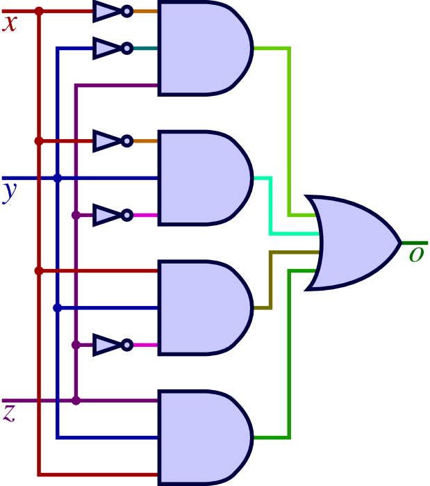
Draw The Logic Circuit For Boolean Expression X Y Xz Wiring Diagram
Web since the inputs and outputs of logic gates are just wires carrying on/off signals, logic gates can be wired together by connecting outputs from some gates to inputs of other gates. Web on the circuit diagram, add temporary letters after each gate (c, d, e in the above example) create a blank truth table, allowing space for all the.

How To Draw Logic Circuit Diagram Wiring Diagram
Open the logic gate shape library to draw the diagram by dragging and dropping the components on to the canvas. Boolean algebra expression simplifier & solver. Web #logicdiagram#logiccircuit#booleanexpressionthis video will help you to learn how to draw a logic circuit from given boolean expression or boolean functionth. The gates need to be arranged so that the distance between connected gates.

DRAWING LOGIC CIRCUIT USING EXPRESSION LSTOU EDUCATION YouTube
Circuits enables computers to do more complex operations than they could accomplish with just a single gate. No matter you want a logic diagram tool for teaching, or a logic circuit software for engineering purposes, our online logic diagram. A start / stop button (b). Computers need a way to manipulate those 1s and 0s, so that they can eventually.

Draw The Logic Circuit For Boolean Expression X Y Xz Wiring Diagram
Web boolean algebra finds its most practical use in the simplification of logic circuits. While visualizing the single gates and the wires are relatively simple, arranging the elements on the canvas is challenging: Boolean algebra expression simplifier & solver. Where these signals originate is of no concern in the task of gate reduction. Computers use logic gates to transform the.

How to draw a logic statement GCSE Computer Science tutorial YouTube
Web we call that a logic circuit. Logigators' editor can handle even the largest projects with ease thanks to webassembly and webgl. Web boolean algebra expression simplifier & solver. An example is also shown in figure 1.3. The safety button must be pressed (and maintained) before the start / stop button is pushed to start the mot

Draw a ladder logic circuits that implement the logic functions shown
The logic circuit in the figure has three inputs, labeled a, b, a, b, and c c. Where these signals originate is of no concern in the task of gate reduction. Browse circuits made by other users of circuit diagram. A signal to run the motor (m). Web first you will need to learn the shapes/symbols used to draw the.
(Click On The Following Equations To Draw Their Logic Gates Diagrams) Logic Gates Diagram Creatorcreate Your Own Logic Gates Diagram.
You need to be able to draw a circuit diagram by hand, but there are plenty of online tools that you can use to practise your skills. A signal to run the motor (m). Web build and simulate circuits right in your browser. Use our logic gates diagram tool to create the diagrams as follow:
From Simple Gates To Complex Sequential Circuits, Plot Timing Diagrams, Automatic Circuit Generation, Explore Standard Ics, And Much More.
If we translate a logic circuit’s function into symbolic (boolean) form, and apply certain algebraic rules to the resulting equation to reduce the number of terms and/or arithmetic operations, the simplified equation may be translated back into circuit form for a logic circuit. The output of the and gate goes to an or gate. You can see an example of each logic gate here. Web logic and gate tutorial.
Web On The Circuit Diagram, Add Temporary Letters After Each Gate (C, D, E In The Above Example) Create A Blank Truth Table, Allowing Space For All The Temporary Letters (Stages) Write Into The Truth Table All The Possible Unique Input Combinations (A And B Combinations In This Example) In The Truth Table, Calculate The Output At Each Temporary.
The logic gate software has all the logic symbols you need to design any kind of logic model. You can also choose a premade creately logic gate diagram template that. The smallest circuit is a chain of 2 logic gates. We send information through computers using wires that represent 1s and 0s.
Web Open Creately And Create Your Workspace.
No matter you want a logic diagram tool for teaching, or a logic circuit software for engineering purposes, our online logic diagram. The safety button must be pressed (and maintained) before the start / stop button is pushed to start the mot These often have the advantage that you can. A start / stop button (b).