Draw The Shear And Moment Diagrams For The Beam Shown
Draw The Shear And Moment Diagrams For The Beam Shown - We go through breaking a beam into segments, and then we learn about the relatio. Web draw the shear force and bending moment diagrams for the beam shown below. Sectional area ix ly sx sy (cm) (cm) (cm³) (cm³) 80 kn/m hinge 160 kn d (cm²) e h 76.1 12860 1829 849. Web draw the shear and moment diagrams for the beam shown. (20 points) hinge 3 k/ft a с b 20 ft 20 ft 6 ft. V(x) = vr = p = constant. 13.27 for the beams shown, draw complete shear and moment diagrams. 480 views 4 months ago chapter 6 (bending) by mechanics of materials r.c hibbeler (9th edition), complete solution by engr adnan rasheed mechanical. This video explains how to draw shear force diagram and bending moment diagram with easy steps for a simply. Determine all the reactions on the beam.
This can be done by creating a shear and bending moment diagram. Shear and moment diagrams and formulas are excerpted from the western woods use book, 4th edition, and are provided herein as a courtesy of. We go through breaking a beam into segments, and then we learn about the relatio. This problem has been solved! Web shear and moment equations and diagrams for beams. Web below is a simple example of what shear and moment diagrams look like, afterwards, the relation between the load on the beam and the diagrams will be discussed. Web draw the shear and moment diagrams for the beam shown. Web transcribed image text: This problem has been solved! The shear and bending moment at x are then.
I have the answers (see below) but need assistance with the steps to get to them. Web draw the shearing force and bending moment diagrams for the cantilever beam subjected to a uniformly distributed load in its entire length, as shown in figure 4.5a. Shear and bending moment equations. Figures 1 through 32 provide a series of shear and moment diagrams with accompanying formulas for design of beams under various static loading conditions. Also, draw shear and moment diagrams, specifying values at all change of loading positions and at. (20 points) hinge 3 k/ft a с b 20 ft 20 ft 6 ft. Web draw the shear and moment diagrams for the beam, and determine the shear and moment throughout the beam as functions of x. Once these are determined, derive the shear and moment functions. This problem has been solved! This problem has been solved!

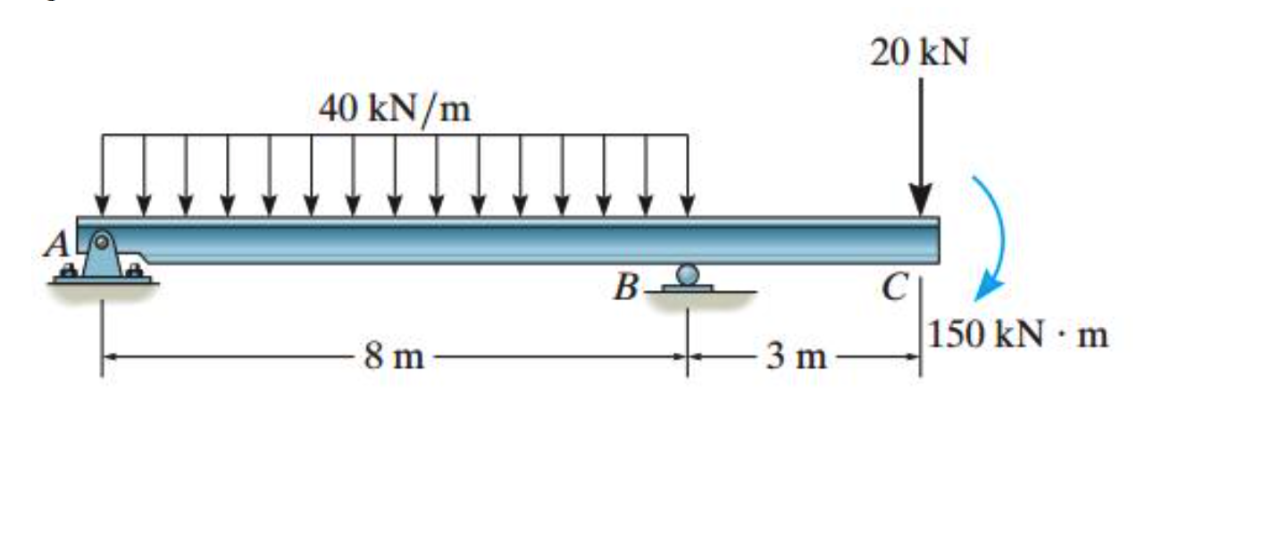
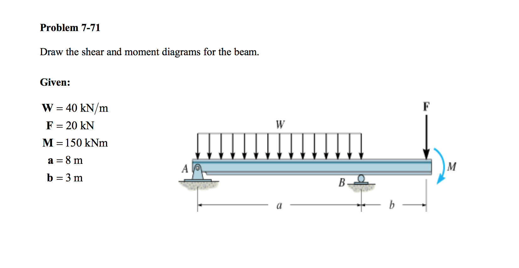
Statics 7.71 Draw the shear and moment diagram for the beam. YouTube
In general the process goes like this: The beginning, end, or change of a load pattern. Learn to draw shear force and moment diagrams using 2 methods, step by step. Web in order to construct shear and moment diagrams for a beam, first, determine the reactive forces and couple moments acting on the beam, and resolve all the forces into.

Solved Draw the shear and moment diagrams for the beam, and
Also, draw shear and moment diagrams, specifying values at all change of loading positions and at. Web learning by teaching. Once these are determined, derive the shear and moment functions. Web write shear and moment equations for the beams in the following problems. This can be done by creating a shear and bending moment diagram.

Solved Draw the shear and moment diagrams for the beam.
Mechanical engineering questions and answers. We go through breaking a beam into segments, and then we learn about the relatio. Divide the beam (of length l) into n segments. A)vmax=‐61.3k, mmax=+463k‐ft b) vmax=‐31.5k, mmax=+155.1k‐ft. Draw the shear and moment diagram for the beam shown below.
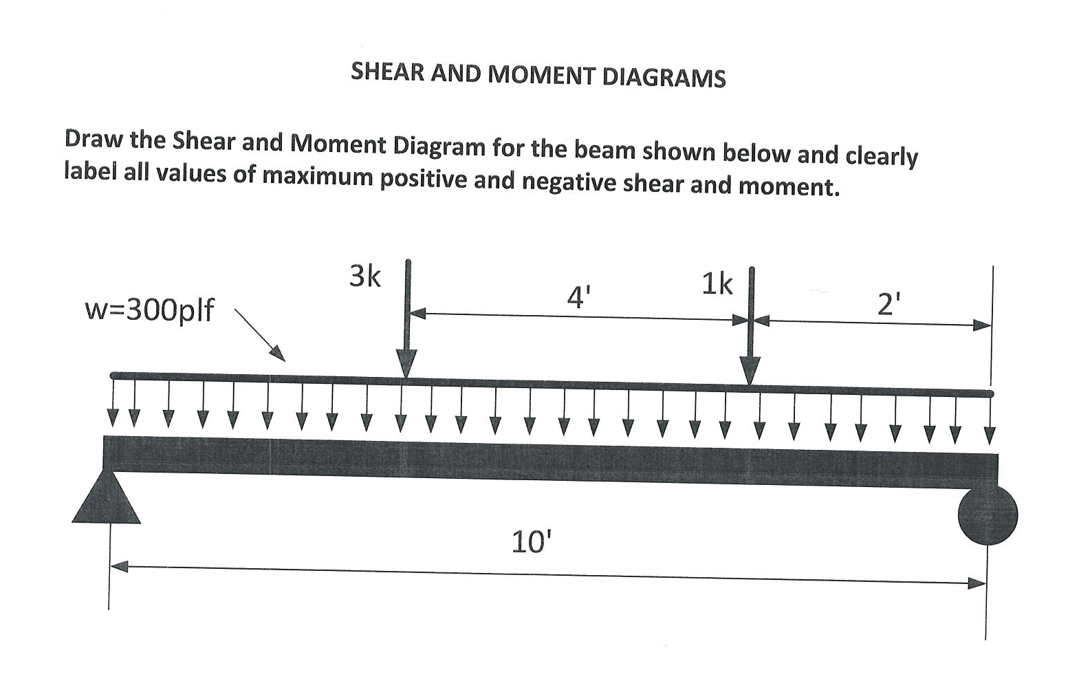
Solved Draw the Shear and Moment Diagram for the beam shown
Also, draw shear and moment diagrams, specifying values at all change of loading positions and at. Web calculate shear force diagrams. Figures 1 through 32 provide a series of shear and moment diagrams with accompanying formulas for design of beams under various static loading conditions. Shear and bending moment equations. In general the process goes like this:

Shear and moment diagrams geekloki
Web in order to construct shear and moment diagrams for a beam, first, determine the reactive forces and couple moments acting on the beam, and resolve all the forces into components acting perpendicular and parallel to the beam’s axis. Once these are determined, derive the shear and moment functions. For the beam of figure 4: A) determine the reactions at.

Solved Draw the shear and moment diagrams for the beam (a)
Web transcribed image text: Once these are determined, derive the shear and moment functions. Clearly show the peak shear and bending moment values and their locations along the beam. In each problem, let x be the distance measured from left end of the beam. Web shear and moment equations and diagrams for beams.
Solved Draw the shear and moment diagrams for the beam.
For the beam of figure 4: Once these are determined, derive the shear and moment functions. Web draw the shear force and bending moment diagrams for the beam shown below. Web below is a simple example of what shear and moment diagrams look like, afterwards, the relation between the load on the beam and the diagrams will be discussed. Web.
Solved Draw the shear and moment diagrams for the beam using
Clearly show the peak shear and bending moment values and their locations along the beam. Web write shear and moment equations for the beams in the following problems. How to use skyciv beam calculator. Welcome to our free beam calculator! Internal forces in beams and frames, libretexts.

Learn How To Draw Shear Force And Bending Moment Diagrams Engineering
Web draw the shear force and bending moment diagrams for the beam shown below. Mechanical engineering questions and answers. ∑fy = 0 = −vr + p ⇒ vr = p. Web in order to construct shear and moment diagrams for a beam, first, determine the reactive forces and couple moments acting on the beam, and resolve all the forces into.
Solved Draw the shear and moment diagrams for the beam.
Web below is a simple example of what shear and moment diagrams look like, afterwards, the relation between the load on the beam and the diagrams will be discussed. This problem has been solved! 172k views 5 years ago civil engineering/structural engineering. Mechanical engineering questions and answers. Civil engineering questions and answers.
In Each Problem, Let X Be The Distance Measured From Left End Of The Beam.
Web learning by teaching. 13.27 for the beams shown, draw complete shear and moment diagrams. Web establish the m and x axes and plot the values of the moment at the ends of the beam. Web transcribed image text:
Shear And Moment Diagrams And Formulas Are Excerpted From The Western Woods Use Book, 4Th Edition, And Are Provided Herein As A Courtesy Of.
This video explains how to draw shear force diagram and bending moment diagram with easy steps for a simply. Web calculate shear force diagrams. A) determine the reactions at the supports. Civil engineering questions and answers.
Web Draw The Shear And Moment Diagrams For The Beam, And Determine The Shear And Moment Throughout The Beam As Functions Of X.
Once these are determined, derive the shear and moment functions. This problem has been solved! The shear and bending moment at x are then. V(x) = vr = p = constant.
Welcome To Our Free Beam Calculator!
Web the previous section presented a method to find the shear and bending moment at a single point, which is useful; Web draw the shear force and bending moment diagrams for the beam shown below. 1) calculate support reactions 2). Web draw the shearing force and bending moment diagrams for the cantilever beam subjected to a uniformly distributed load in its entire length, as shown in figure 4.5a.