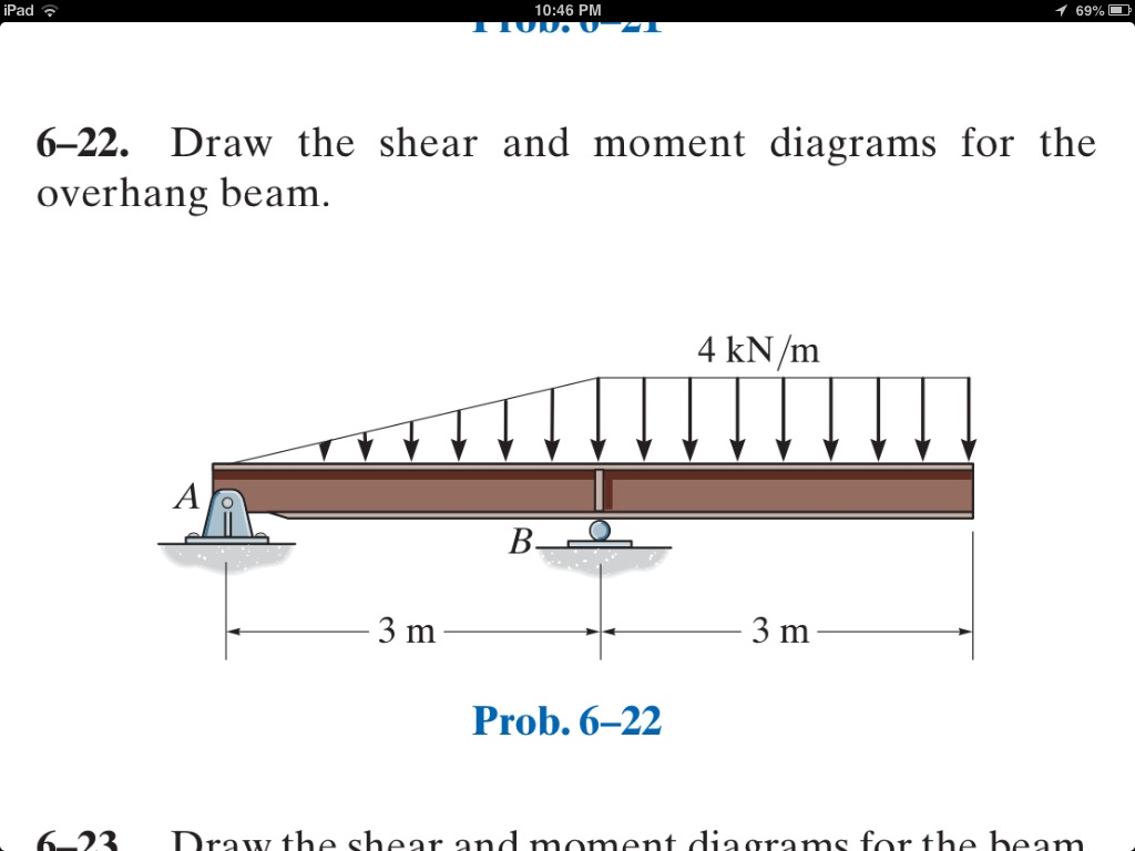
Draw The Shear And Moment Diagrams For The Overhang Beam
Draw The Shear And Moment Diagrams For The Overhang Beam - Shear and moment diagrams and formulas are excerpted from the western woods use book, 4th edition, and are provided herein as a courtesy of western wood products association. Web draw the shear and moment diagrams for the overhang beam. There are 2 steps to solve this one. Web figures 1 through 32 provide a series of shear and moment diagrams with accompanying formulas for design of beams under various static loading conditions. Overhanging beam is a type of beam, where both the ends of the beam are hanging. Also, draw shear and moment diagrams, specifying values at all change of loading positions and at. Mmax = 84 knm, σmax = 98.9 mpa. Draw shear and moment diagram for the overhanging beam shown below, and then draw the elastic curve based on moment diagram. They allow us to see where the maximum loads occur so that we can optimize the design to prevent failures and reduce the overall weight and cost of the structure. Web calculate the shear force and bending moment values due to the imposed loading on the overhanging beam of figure 1.
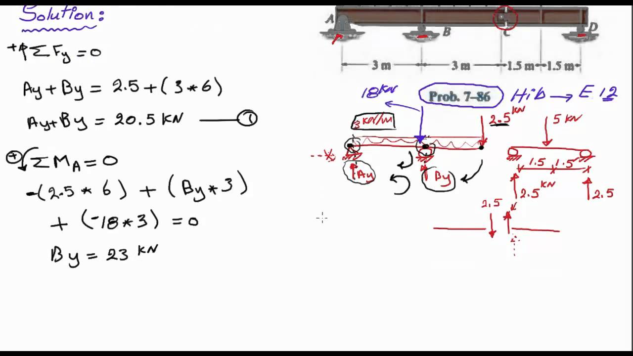
Web describes how to draw shear and moment diagrams graphically for a beam with an overhang.0:30 calculate support reactions2:48 describe the process for drawing. Web ay this will allow you to find external ex bx' bx' bx bx by' by' by by cy ey reaction forces at the supports and internal reaction forces at the hinge. You'll get a detailed solution from a subject matter expert that helps you learn core concepts. Web draw the shear and moment diagrams for the beam, and determine the shear and moment throughout the beam as functions of x. Web you'll get a detailed solution from a subject matter expert that helps you learn core concepts. Overhanging beam is a type of beam, where both the ends of the beam are hanging. Web this video shows how to draw the shear force and bending moment diagram for overhanging beam. There are 3 steps to solve this one. Web the first step in calculating these quantities and their spatial variation consists of constructing shear and bending moment diagrams, \(v(x)\) and \(m(x)\), which are the internal shearing forces and bending moments induced in. Shear and moment diagrams and formulas are excerpted from the western woods use book, 4th edition, and are provided herein as a courtesy of western wood products association.
Web in this chapter, the student will learn how to determine the magnitude of the shearing force and bending moment at any section of a beam or frame and how to present the computed values in a graphical form, which is referred to as the “shearing force” and the “bending moment diagrams.” Web figures 1 through 32 provide a series of shear and moment diagrams with accompanying formulas for design of beams under various static loading conditions. Shear and moment diagrams and formulas are excerpted from the western woods use book, 4th edition, and are provided herein as a courtesy of western wood products association. Web you'll get a detailed solution from a subject matter expert that helps you learn core concepts. Web ay this will allow you to find external ex bx' bx' bx bx by' by' by by cy ey reaction forces at the supports and internal reaction forces at the hinge. 80% (5 ratings) share share. In case of overhanging beam, the bm is positive between the two supports, whereas the bm is negative for the overhanging portion. Web describes how to draw shear and moment diagrams graphically for a beam with an overhang.0:30 calculate support reactions2:48 describe the process for drawing. The beam having its portion is extended beyond the support, such beam is known as overhanging beam. Web write shear and moment equations for the beams in the following problems.
[Solved] Draw the shear and moment diagrams for the overhang beam. 9 KN
You'll get a detailed solution from a subject matter expert that helps you learn core concepts. Web draw the shearing force and bending moment diagrams for the cantilever beam subjected to a uniformly distributed load in its entire length, as shown in figure 4.5a. You'll get a detailed solution from a subject matter expert that helps you learn core concepts..
Draw The Shear And Moment Diagrams For The Overhang Beam. Wiring
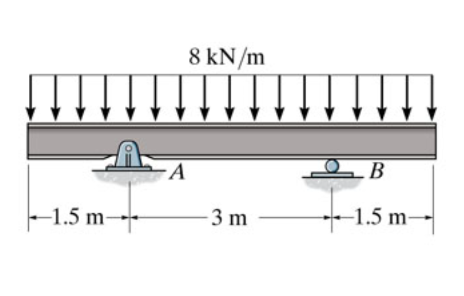
This problem has been solved! In case of overhanging beam, the bm is positive between the two supports, whereas the bm is negative for the overhanging portion. Emphasize the understanding of beam reactions, internal forces, and equilibrium equations. Web draw the shearing force and bending moment diagrams for the cantilever beam subjected to a uniformly distributed load in its entire.

Draw The Shear Diagram For The Beam
The beam’s reactions are calculated as: In case of overhanging beam, the bm is positive between the two supports, whereas the bm is negative for the overhanging portion. Web the first step in calculating these quantities and their spatial variation consists of constructing shear and bending moment diagrams, \(v(x)\) and \(m(x)\), which are the internal shearing forces and bending moments.
Solved Draw the shear and moment diagrams for the overhang
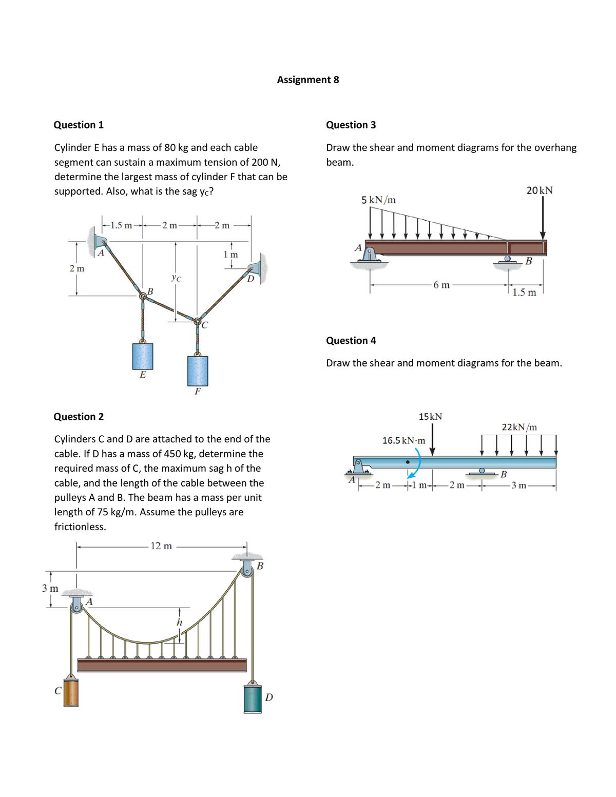
Web calculate the shear force and bending moment values due to the imposed loading on the overhanging beam of figure 1. Web draw the shear and moment diagrams for the beam, and determine the shear and moment throughout the beam as functions of x. Web write shear and moment equations for the beams in the following problems. Web describes how.
Draw The Shear And Moment Diagrams For Overhang Beam 6 22 Home
In case of overhanging beam, the bm is positive between the two supports, whereas the bm is negative for the overhanging portion. In each problem, let x be the distance measured from left end of the beam. Web describes how to draw shear and moment diagrams graphically for a beam with an overhang.0:30 calculate support reactions2:48 describe the process for.
Draw The Shear And Moment Diagrams For The Double Overhanging Beam
Web our calculator generates the reactions, shear force diagrams (sfd), bending moment diagrams (bmd), deflection, and stress of a cantilever beam or simply supported beam. Web figures 1 through 32 provide a series of shear and moment diagrams with accompanying formulas for design of beams under various static loading conditions. They allow us to see where the maximum loads occur.

Shear force & Bending moment diagram for Overhanging Beam YouTube
They allow us to see where the maximum loads occur so that we can optimize the design to prevent failures and reduce the overall weight and cost of the structure. Overhanging beam is a type of beam, where both the ends of the beam are hanging. Draw the shear and moment diagrams for the overhang beam. For more details please.
Draw The Shear And Moment Diagrams For Overhang Beam 6 22 Home
There are 3 steps to solve this one. Draw the shear and moment diagrams for the overhang beam. This problem has been solved! These would be represented through shear and bending moment diagrams, shown below. The beam having its portion is extended beyond the support, such beam is known as overhanging beam.
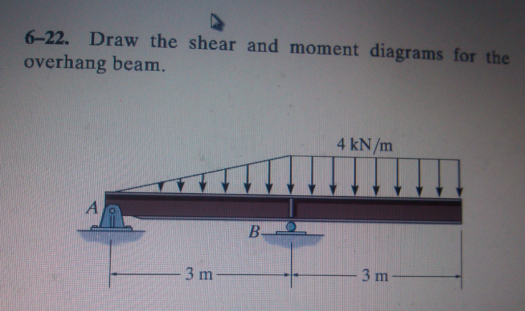
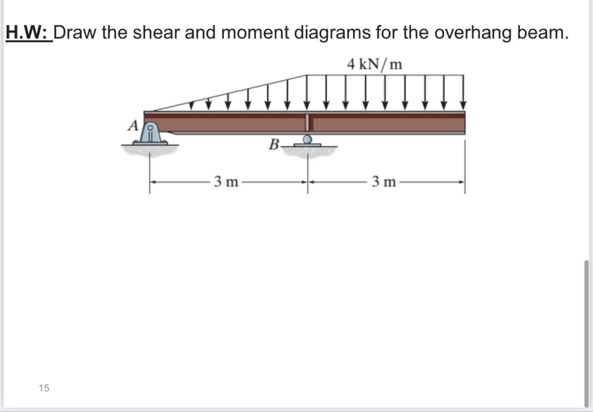
Draw the shear and moment diagrams for the overhang beam.
Web this video shows how to draw the shear force and bending moment diagram for overhanging beam. Draw shear and moment diagram for the overhanging beam shown below, and then draw the elastic curve based on moment diagram. This problem has been solved! They allow us to see where the maximum loads occur so that we can optimize the design.

Shear Force & Bending Moment Diagram for Overhanging Beam YouTube
Emphasize the understanding of beam reactions, internal forces, and equilibrium equations. Web once the reactions are calculated, the shear force (v) and bending moment (m) distributions along the beam can be determined. Also, draw shear and moment diagrams, specifying values at all change of loading positions and at. Overhanging beam is a type of beam, where both the ends of.
80% (5 Ratings) Share Share.
Skyciv beam tool guides users along a professional beam calculation workflow, culminating in the ability to view and determine if they comply with your region's design codes. There are 3 steps to solve this one. Shear and moment diagrams and formulas are excerpted from the western woods use book, 4th edition, and are provided herein as a courtesy of western wood products association. Web draw the shearing force and bending moment diagrams for the cantilever beam subjected to a uniformly distributed load in its entire length, as shown in figure 4.5a.
Web This Video Shows How To Draw Shear Force And Bending Moment Diagram For Overhanging Beam.
Draw shear and moment diagram for the overhanging beam shown below, and then draw the elastic curve based on moment diagram. Web once the reactions are calculated, the shear force (v) and bending moment (m) distributions along the beam can be determined. Web the first step in calculating these quantities and their spatial variation consists of constructing shear and bending moment diagrams, \(v(x)\) and \(m(x)\), which are the internal shearing forces and bending moments induced in. In case of overhanging beam, the bm is positive between the two supports, whereas the bm is negative for the overhanging portion.
There Are 3 Steps To Solve This One.
Web draw the shear and moment diagrams for the beam, and determine the shear and moment throughout the beam as functions of x. Web shear and moment diagrams are graphs which show the internal shear and bending moment plotted along the length of the beam. Web describes how to draw shear and moment diagrams graphically for a beam with an overhang.0:30 calculate support reactions2:48 describe the process for drawing. Also, draw shear and moment diagrams, specifying values at all change of loading positions and at.
Web Our Calculator Generates The Reactions, Shear Force Diagrams (Sfd), Bending Moment Diagrams (Bmd), Deflection, And Stress Of A Cantilever Beam Or Simply Supported Beam.
Overhanging beam is a type of beam, where both the ends of the beam are hanging. Emphasize the understanding of beam reactions, internal forces, and equilibrium equations. These would be represented through shear and bending moment diagrams, shown below. Web in this chapter, the student will learn how to determine the magnitude of the shearing force and bending moment at any section of a beam or frame and how to present the computed values in a graphical form, which is referred to as the “shearing force” and the “bending moment diagrams.”