Draw The Shear Diagram For The Beam
Draw The Shear Diagram For The Beam - Shear and bending moment equations. Equation 6.1 suggests the following expression: Write shear and moment equations for the beams in the following problems. Part b draw the moment diagram for the beam. ∑fy = 0 = −vr + p ⇒ vr = p. Draw the shear and moment diagrams for the beam. 172k views 5 years ago civil engineering/structural engineering. Write equations for the shear v and bending moment m for any section of the beam in the interval ab. You'll get a detailed solution from a subject matter expert that helps you learn core concepts. Web the shear diagram will plot out the internal shearing forces within a beam, or other body that is supporting multiple forces perpendicular to the length of the beam or body itself.
Internal forces in beams and frames, libretexts. The shear and bending moment at x are then. Determine all the reactions on the beam. Web when designing a beam it is important to locate the points of maximum shear and maximum moment and their magnitudes because that’s where the beam is most likely to fail. In general the process goes like this: You'll get a detailed solution from a subject matter expert that helps you learn core concepts. The beam is loaded and supported as shown in the figure. 200lb 100lb 250lb 100lb 0 250 lbrc We go through breaking a beam into segments, and then we learn about the relationships between shear force and. This video explains how to draw shear force diagram and bending moment diagram with easy steps for a simply supported.
We go through breaking a beam into segments, and then we learn about the relationships between shear force and. Web you will be fully competent in drawing shear force and bending moment diagrams for statically determinate beams and frames. Web the equation also suggests that the slope of the moment diagram at a particular point is equal to the shear force at that same point. Write shear and moment equations for the beams in the following problems. Internal forces in beams and frames, libretexts. Draw the shear and moment diagrams for the beam. The beam is loaded and supported as shown in the figure. Web when designing a beam it is important to locate the points of maximum shear and maximum moment and their magnitudes because that’s where the beam is most likely to fail. Web shear and moment equations and diagrams for beams. Also, draw shear and moment diagrams, specifying values at all change of loading positions and at points of zero shear.
Solved Draw the shear diagram for the beam. Follow
In each problem, let x be the distance measured from left end of the beam. Web beam guru.com is a online calculator that generates bending moment diagrams (bmd) and shear force diagrams (sfd), axial force diagrams (afd) for any statically determinate (most simply supported and cantilever beams) and statically indeterminate beams, frames and trusses. We go through breaking a beam.

Learn How To Draw Shear Force And Bending Moment Diagrams Engineering
To find these weak points, we need to check the internal loading at every point along the beam’s full length. Equation 6.1 suggests the following expression: [latex]\delta m=\int v (x)dx [/latex] (equation 6.2) equation 6.2 states that the change in moment equals the area under the shear diagram. Part b draw the moment diagram for the beam. Write equations for.

Solved Draw the shear and moment diagrams for the beam.
Neglect the mass of the beam in each problem. In each problem, let x be the distance measured from left end of the beam. Web the equation also suggests that the slope of the moment diagram at a particular point is equal to the shear force at that same point. In this experiment, we will work on drawing the shear.

Shear Force and Bending Moment diagram of Beam with Triangular Load
Shear and bending moment equations. Web shear and moment equations and diagrams for beams. Divide the beam (of length l) into n segments. How to use skyciv beam calculator. ∑fy = 0 = −vr + p ⇒ vr = p.

Mechanics Map Shear and Moment Diagrams
172k views 5 years ago civil engineering/structural engineering. Web the shear diagram will plot out the internal shearing forces within a beam, or other body that is supporting multiple forces perpendicular to the length of the beam or body itself. V(x) = vr = p = constant. You will have a robust system of analysis that allows you to confidently.

Brief Information About Shear Force And Bending Moment Diagrams
How to use skyciv beam calculator. Try our free beam calculator today! Web egr2312 lab experiment n°8 shearing and bending moment diagrams 1. You'll get a detailed solution from a subject matter expert that helps you learn core concepts. The beginning, end, or change of a load pattern.

Shear and moment diagrams geekloki
1) calculate support reactions 2) draw. Web below is a simple example of what shear and moment diagrams look like, afterwards, the relation between the load on the beam and the diagrams will be discussed. You'll get a detailed solution from a subject matter expert that helps you learn core concepts. (45in.) 100 lb(15in.) 250 lb(20 in.) 100 lb(55in.) 0r.

Beam shear and bending moment diagrams sekajava
Web egr2312 lab experiment n°8 shearing and bending moment diagrams 1. Draw the shear and moment diagrams for the beam. ∑fy = 0 = −vr + p ⇒ vr = p. Web this is an example problem that will show you how to graphically draw a shear and moment diagram for a beam. The beam is loaded and supported as.

Learn How To Draw Shear Force And Bending Moment Diagrams Engineering
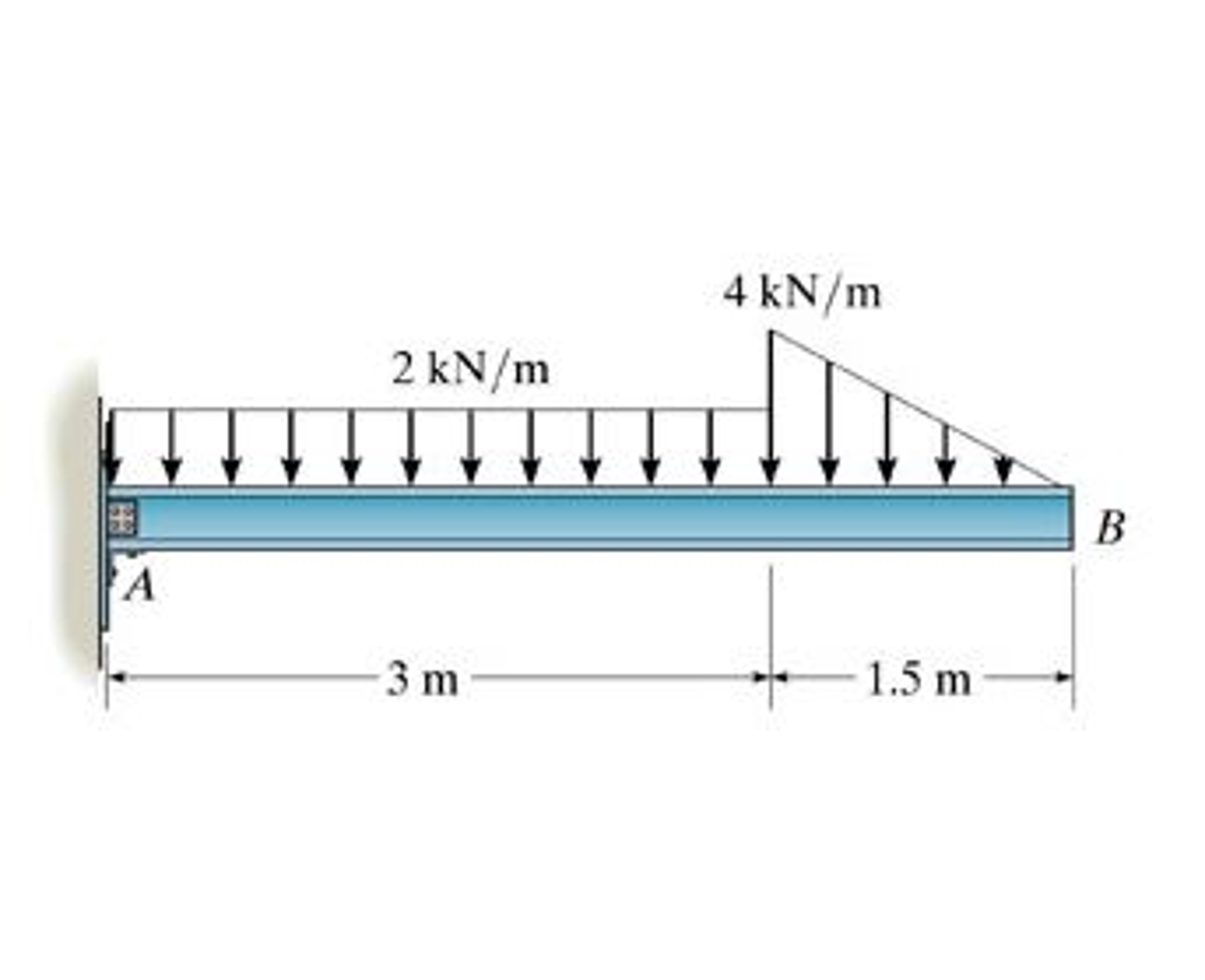
Mechanical engineering questions and answers. Problem 7.81 part a draw the shear diagram for the beam. Web when designing a beam it is important to locate the points of maximum shear and maximum moment and their magnitudes because that’s where the beam is most likely to fail. Our calculator generates the reactions, shear force diagrams (sfd), bending moment diagrams (bmd),.

Draw The Shear Diagram For The Beam Set P 800 Lb A 5 Ft L 12 Ft Free
200lb 100lb 250lb 100lb 0 250 lbrc Internal forces in beams and frames, libretexts. Web below is a simple example of what shear and moment diagrams look like, afterwards, the relation between the load on the beam and the diagrams will be discussed. The beam is loaded and supported as shown in the figure. Mechanical engineering questions and answers.
1) Calculate Support Reactions 2) Draw.
In this diagram, the horizontal axis represents the length of the structural element, while the vertical axis represents the magnitude and direction of the shear forces. In each problem, let x be the distance measured from left end of the beam. Web egr2312 lab experiment n°8 shearing and bending moment diagrams 1. Web draw the shear force and bending moment diagrams for the frame subjected to the loads shown in figure 4.10a.
The Beginning, End, Or Change Of A Load Pattern.
For the beam of figure 4: In general the process goes like this: 200lb 100lb 250lb 100lb 0 250 lbrc You'll get a detailed solution from a subject matter expert that helps you learn core concepts.
Part B Draw The Moment Diagram For The Beam.
Web below is a simple example of what shear and moment diagrams look like, afterwards, the relation between the load on the beam and the diagrams will be discussed. Try our free beam calculator today! Neglect the mass of the beam in each problem. Problem 7.81 part a draw the shear diagram for the beam.
The Beam Is Loaded And Supported As Shown In The Figure.
This video explains how to draw shear force diagram and bending moment diagram with easy steps for a simply supported. Dear viewer you can find more videos in the link given below to learn more and moretheory video lectur. Internal forces in beams and frames, libretexts. Write shear and moment equations for the beams in the following problems.