Drawing Detail View
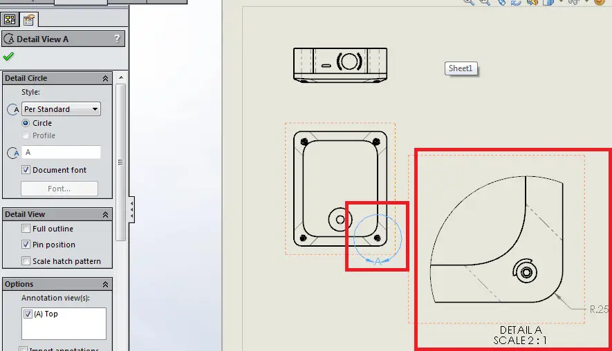
Drawing Detail View - Creating a detail drawing view allows a user to enlarge areas within a drawing view to a different scale. Watch the tech tip video to learn how adding foreshortened diameter dimensions in solidworks detail views is quick and easy with a drag and drop technique. Click detail view (drawing toolbar), or click insert > drawing view > detail. Web create a detail view. On the ribbon, click place views tabcreate panel detail. Click to select an existing view as the parent view. Web sunday night could offer another opportunity to see the northern lights unusually far south, though less than earlier predicted. First, let’s discuss the default option, detail view. Detailing for steel construction, 3rd ed. A detail view is a drawing view that contains a portion of another drawing view and is magnified to a larger scale.
Web types of views. Detail drawings are an essential aspect of engineering, architecture, and. To create a detail view. If needed, click edit view label and edit the detail view label in the format text dialog. Web to create a detail view: You can generate detail views with rectangular or circular borders from any model documentation drawing view. A geomagnetic storm lights up the night sky above the bonneville. The drawing files below are the most current revisions. This command is only supported in the layout and you must. Web village of glenview | residents the village of glenview
Web village of glenview | residents the village of glenview Web the two main types of views (or “projections”) used in drawings are: Web in this video we explore how to create a detail drawing view inside autodesk inventor. In catia v5, you can select to make a detail view area in a circular shape, or a custom shape that the user creates. How to create detail views in autocad? Click to select an existing view as the parent view. There are two alternative ways to created detail views in the layout of autocad. The solar storm was a level 5 on friday, which gave. Detail drawings are an essential aspect of engineering, architecture, and. Watch the tech tip video to learn how adding foreshortened diameter dimensions in solidworks detail views is quick and easy with a drag and drop technique.

How To Prepare A Perfect Technical Drawing Xometry Europe
Creating a detail drawing view allows a user to enlarge areas within a drawing view to a different scale. I also go over some tips i've learned from my own experience with usi. Bottom line is to make the drawing as easy to interpret, within the standards (company, iso or asme), as you reasonably can. Here is a video demonstrating.

How to prepare a technical drawing for CNC machining 3D Hubs
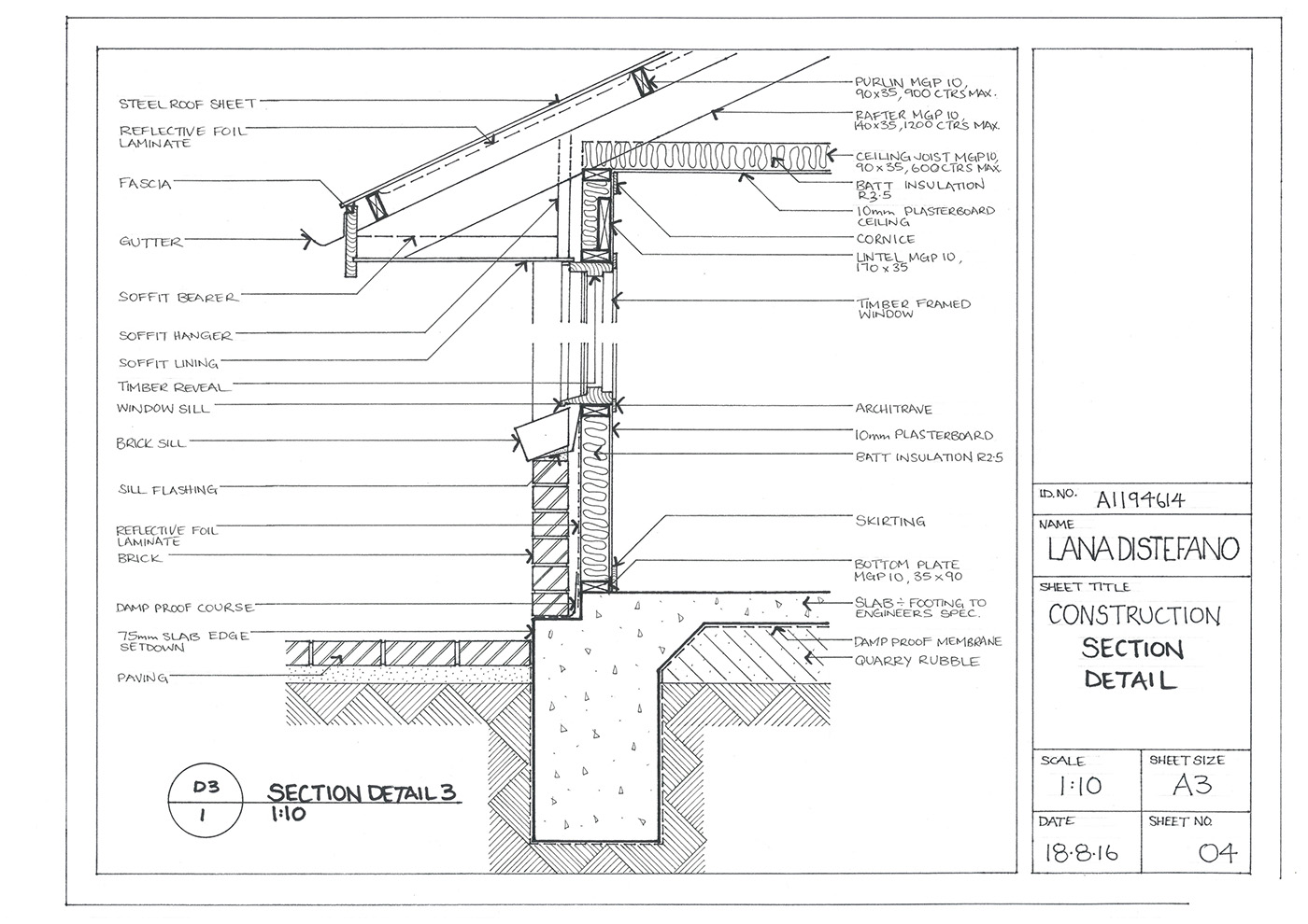
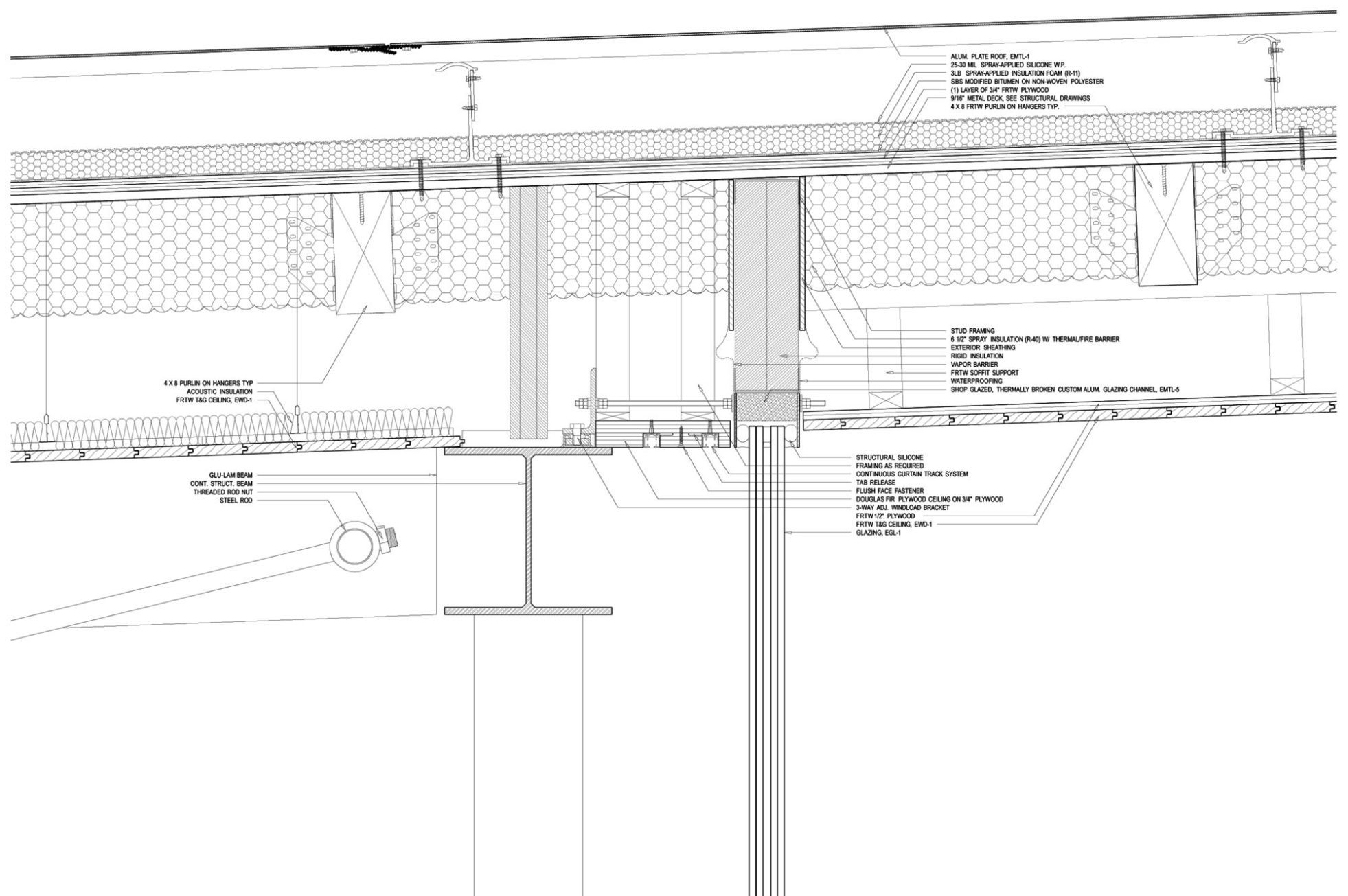
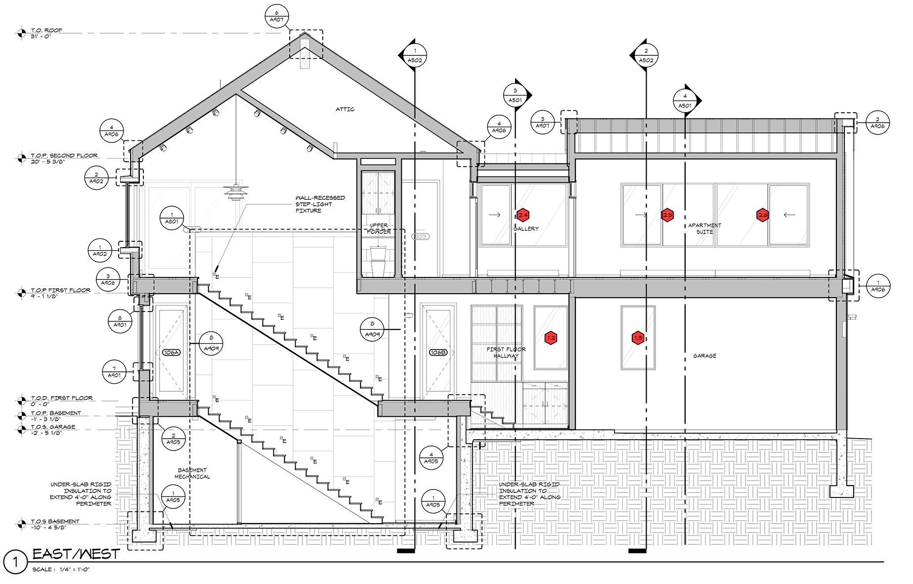
This can be especially useful if an otherwise large part includes many important dimensions in a small area. Web engineering drawing is a specialized form of communication that uses a strict set of symbols, standards, and perspectives to depict mechanical, electrical, or structural designs. Web these drawings show the details of various construction items and are used in conjunction with.
HandDrawn Construction Drawings on Behance
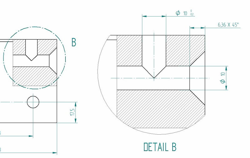
Pull the pointer away from the whole to create a circle around the feature. The solar storm was a level 5 on friday, which gave. Web every detail view should be marked with a capital letter placed near the viewing line and above the detail. And face of curb & bd02.dgn bd03.dgn bd05. To create a detail view.
Young Architect Guide 5 Tips for Drawing Accurate Architectural Details
When you think the circle is big enough, click again to create a preview. Viewdetail (command) creates a detail view of a portion of a model documentation drawing view. There are three types of pictorial views: In catia v5, you can select to make a detail view area in a circular shape, or a custom shape that the user creates..
Detail Drawings Plans, Section, Detail. PROJECT UMBRA on Behance
First, let’s discuss the default option, detail view. Bottom line is to make the drawing as easy to interpret, within the standards (company, iso or asme), as you reasonably can. Detail drawings are an essential aspect of engineering, architecture, and. Web the two main types of views (or “projections”) used in drawings are: Click detail view (drawing toolbar), or click.
Engineering Drawing Views & Basics Explained Fractory
The solar storm was a level 5 on friday, which gave. Web the two main types of views (or “projections”) used in drawings are: Detailing for steel construction, 3rd ed. Bottom line is to make the drawing as easy to interpret, within the standards (company, iso or asme), as you reasonably can. The front view is the first view that.

Create Detail View in Drawing Sheet (Autodesk Inventor) YouTube
Navigate to district specific standards to view specific drawings that pertain to idot. Watch the tech tip video to learn how adding foreshortened diameter dimensions in solidworks detail views is quick and easy with a drag and drop technique. This can be especially useful if an otherwise large part includes many important dimensions in a small area. Also, considering that.
3 Useful Types of Drawing Views in SolidWorks
Create a detail view with a rectangular boundary. A geomagnetic storm lights up the night sky above the bonneville. Web in this video we explore how to create a detail drawing view inside autodesk inventor. The front view is the first view that is chosen and is the only view that is arbitrary, that is, the engineer defines (decides) which.

Dimensioning and sectioning in engineering drawing. Engineering Drawing
Web village of glenview | residents the village of glenview Click to select an existing view as the parent view. These drawings are essentially the blueprints or plans for manufacturing a wide array of products and structures. I usually like to add the remark “detail” in front of the reference letter. Web the drawing order may not follow sort order.
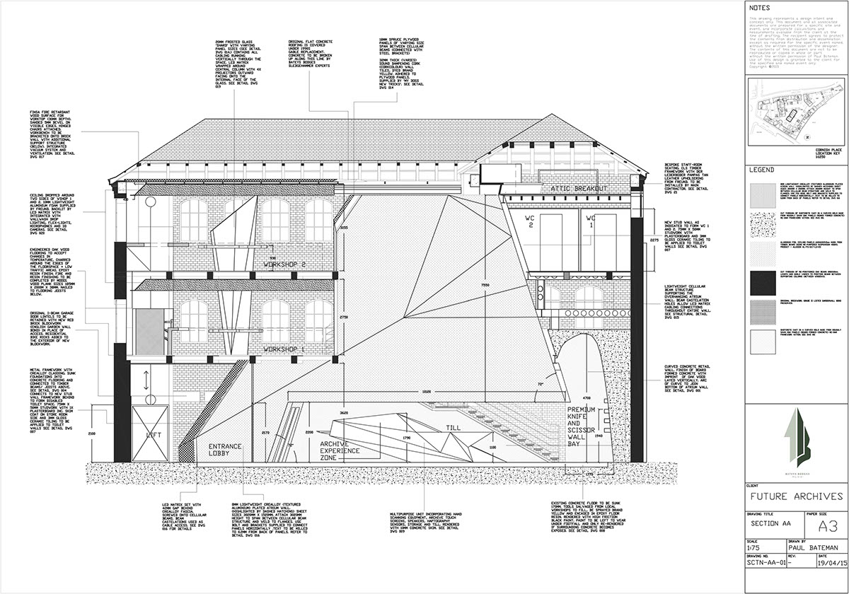
Section Drawing Architecture at Explore collection
Web the drawing order may not follow sort order when the field on color is also on detail. Web engineering drawing is a specialized form of communication that uses a strict set of symbols, standards, and perspectives to depict mechanical, electrical, or structural designs. Here is a video demonstrating these two methods for inserting foreshortened dimensions. This command is only.
To Create A Profile Other Than A Circle, Sketch The.
Web types of views. Isometric view (dimetric and trimetric view) orthographic view (front, side, top, bottom and back views) section view. Here is a video demonstrating these two methods for inserting foreshortened dimensions. There are three types of pictorial views:
Web Engineering Drawing Is A Specialized Form Of Communication That Uses A Strict Set Of Symbols, Standards, And Perspectives To Depict Mechanical, Electrical, Or Structural Designs.
You can have a circular or rectangular detail view. Click detail view (drawing toolbar), or click insert > drawing view > detail. Bottom line is to make the drawing as easy to interpret, within the standards (company, iso or asme), as you reasonably can. When you think the circle is big enough, click again to create a preview.
Select The Top Hole In The Base View To Start The Detail View.
The applicable standards are referenced on the cover sheet of the plans. There are two alternative ways to created detail views in the layout of autocad. Web these drawings show the details of various construction items and are used in conjunction with the standard specifications. On the ribbon, click place views tabcreate panel detail.
The Front View Is The First View That Is Chosen And Is The Only View That Is Arbitrary, That Is, The Engineer Defines (Decides) Which View Will Be The Front View.
This command is only supported in the layout and you must. Web the two main types of views (or “projections”) used in drawings are: Navigate to district specific standards to view specific drawings that pertain to idot. The following are the different types of views often used in engineering drawing: