Drawing Machining Symbols
Drawing Machining Symbols - Check out the uses and images of different roughness symbols below. Symbols used in gd&t callouts. By cnccookbook, the leading cnc blog. Web iso surface roughness symbols. Understand the basic concepts of size and weight information, tolerance, and surface finish as they pertain to machining and the information present on an engineering drawing for machining. Web surface finish symbols are needed to represent the surface texture requirement to manufacturers. This section will explain how to write these symbols to indicate surface textures. Web the table shows dimensioning symbols found on engineering and mechanical drawings. Web symbols that indicate the surface texture of machined and structural parts are used in industrial diagrams. Web symbols for indicating surface finish.
Web you can cut and paste these gd&t symbols into your drawing: Drawing or part number and revision. Symbols indicating target surface and the position of these symbols. Parts of a machining blueprint machining blueprints include the blueprint title block, general tolerance block, projection types and types of feature tolerances. Web in learning to read machine drawings, you must first become familiar with the common terms, symbols, and conventions defined and discussed in the following paragraphs. How to read symbols in an engineering drawing? Geometric dimensioning and tolerancing (gd&t) consists of a set of symbols and rules for applying them that communicates the requirements of an engineering blueprint. This surface roughness indication method pictorially displays information such as the surface roughness value, cutoff value, sampling length, machining method, crease direction symbol, and surface waviness on the surface indication symbol as shown below. Web the table shows dimensioning symbols found on engineering and mechanical drawings. Cut and paste to your drawing.
Download and open the symbol library. By cnccookbook, the leading cnc blog. Surface finish is the nature of a surface as defined by the three characteristics of lay, surface roughness, and waviness. The term “surface finish” is not defined correctly and tends to be used interchangeably by product designers and engineers with surface roughness, surface texture and surface topography. Each symbol is explained with its meaning, variations, and specific applications in manufacturing processes. The following paragraphs cover the common terms most used in all aspects of machine drawings. The title block of a blueprint can vary quite a bit across different companies. Web dive into the secrets of surface finish symbols and start mastering the pros' techniques today! Web in learning to read machine drawings, you must first become familiar with the common terms, symbols, and conventions defined and discussed in the following paragraphs. Web iso surface roughness symbols.
Machining Symbols Chart
Symbols indicating target surface and the position of these symbols. Web explaining different symbols and various lines on a machining drawing. Web basic types of symbols used in engineering drawings are countersink, counterbore, spotface, depth, radius, and diameter. Then you need to specify the surface finish requirement to manufacture. Web standard symbols for mechanical components use such shapes as circles,.

GD&T Symbols Reference Guide from Sigmetrix Mechanical design
Web dive into the secrets of surface finish symbols and start mastering the pros' techniques today! The title block of a blueprint can vary quite a bit across different companies. There are so many different types of drawings, including architectural, mechanical, electrical, etc., that it’s impractical to cover all of them at once. Then you need to specify the surface.

Mechanical Drawing Symbols Electrical Symbols, Electrical Diagram
This list includes abbreviations common to the vocabulary of people who work with engineering drawings in the manufacture and inspection of parts and assemblies. Web gd&t symbols on drawings accurately show dimensions to eliminate confusion and costly rework. Why abbreviations and symbols are needed for engineering drawing? Each symbol is explained with its meaning, variations, and specific applications in manufacturing.
Machine Drawing Symbols
You can also check out the gd&t symbols and terms on our site. Web you can cut and paste these gd&t symbols into your drawing: Why abbreviations and symbols are needed for engineering drawing? Parts of a machining blueprint machining blueprints include the blueprint title block, general tolerance block, projection types and types of feature tolerances. Web examples of different.
machining surface finish symbols triangle Kazuko Deaton
Understand the basic concepts of size and weight information, tolerance, and surface finish as they pertain to machining and the information present on an engineering drawing for machining. Web basic types of symbols used in engineering drawings are countersink, counterbore, spotface, depth, radius, and diameter. The pictorial representation using these symbols is defined in iso 1302:2002. Download and open the.

Machining Drafting Symbols
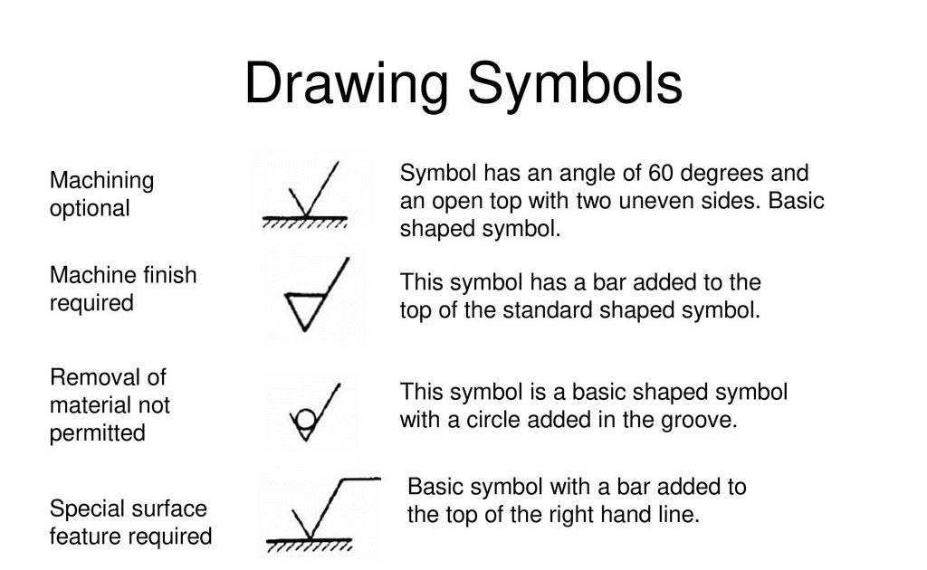
Each symbol is explained with its meaning, variations, and specific applications in manufacturing processes. This basic symbol consists of two legs of unequal length. Web surface finish symbols are needed to represent the surface texture requirement to manufacturers. Web recognize and understand the importance of symbols that appear on, and are often exclusive to, machining drawings. It comes in useful.

Engineering Drawing Symbols And Their Meanings Pdf at PaintingValley
Web gd&t symbols on drawings accurately show dimensions to eliminate confusion and costly rework. How to read symbols in an engineering drawing? Cut and paste to your drawing. Surface roughness symbols are used to communicate the required surface texture of machined and structural parts are used in industrial diagrams. Symbols used in gd&t callouts.

MACHINING SYMBOL AND SURFACE TEXTURE YouTube
Web in learning to read machine drawings, you must first become familiar with the common terms, symbols, and conventions defined and discussed in the following paragraphs. Web recognize and understand the importance of symbols that appear on, and are often exclusive to, machining drawings. This list includes abbreviations common to the vocabulary of people who work with engineering drawings in.

Engineering Drawing Symbols And Their Meanings Pdf at PaintingValley
Most symbols have been in y14.5 since at least 1994. Web you can cut and paste these gd&t symbols into your drawing: Web standard symbols for mechanical components use such shapes as circles, ovals, arcs, triangles, squares, rectangles, polygons, lines, arrows, and other geometrical forms separately or arranged in complex patterns. Web basic types of symbols used in engineering drawings.

Mechanical Engineering Drawing Symbols Pdf Free Download at
Web gd&t symbols on drawings accurately show dimensions to eliminate confusion and costly rework. This list includes abbreviations common to the vocabulary of people who work with engineering drawings in the manufacture and inspection of parts and assemblies. Geometric dimensioning and tolerancing (gd&t) consists of a set of symbols and rules for applying them that communicates the requirements of an.
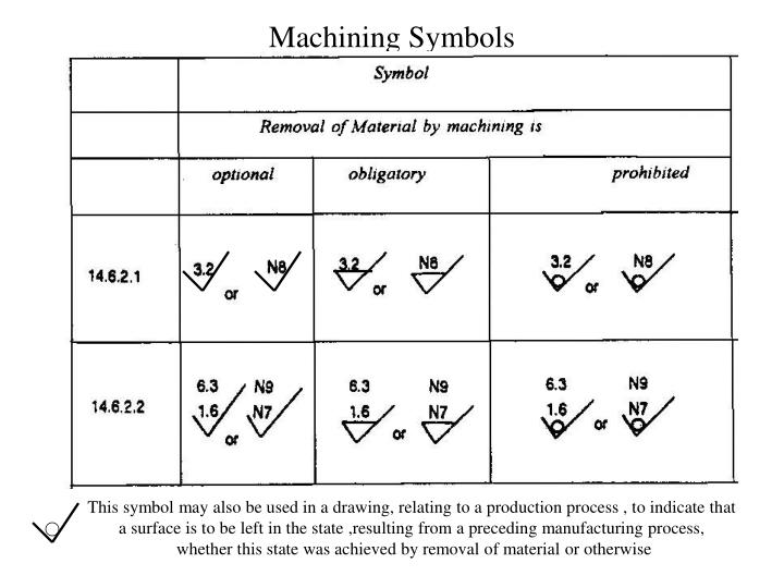
This Surface Roughness Indication Method Pictorially Displays Information Such As The Surface Roughness Value, Cutoff Value, Sampling Length, Machining Method, Crease Direction Symbol, And Surface Waviness On The Surface Indication Symbol As Shown Below.
Web basic types of symbols used in engineering drawings are countersink, counterbore, spotface, depth, radius, and diameter. You can use surface finish symbols to tell the manufacturer about your. Web engineering drawing abbreviations and symbols are used to communicate and detail the characteristics of an engineering drawing. Common engineering drawing abbreviations used in cnc machining.
Web Dive Into The Secrets Of Surface Finish Symbols And Start Mastering The Pros' Techniques Today!
Web in learning to read machine drawings, you must first become familiar with the common terms, symbols, and conventions defined and discussed in the following paragraphs. The pictorial representation using these symbols is defined in iso 1302:2002. Symbols used in gd&t callouts. The term “surface finish” is not defined correctly and tends to be used interchangeably by product designers and engineers with surface roughness, surface texture and surface topography.
An Introduction To The Different Types Of Blueprint Tolerances You Will Encounter With Plenty Of Examples To Make Them Easy To Understand.
Gd&t controls variations of size, form, orientation, location and runout individually or in combination. By cnccookbook, the leading cnc blog. Then you need to specify the surface finish requirement to manufacture. Download and open the symbol library.
Note The Comparison With The Iso Standards.
Drawing or part number and revision. Web symbols that indicate the surface texture of machined and structural parts are used in industrial diagrams. Web surface finish symbols are needed to represent the surface texture requirement to manufacturers. Web iso surface roughness symbols.