Drawing Symbol
Drawing Symbol - Learning to read blueprints can be hard. Web drafting symbols symbols provide a “common language” for drafters all over the world. In the design industry, there are standardized line types and correct techniques to be used for producing professionally hand drafted drawings. The symbols represent electrical and electronic components. Web — 11 min read. In this chapter we will study what constitutes good drafting technique for each line type. Web electrical symbols and electronic circuit symbols are used for drawing schematic diagram. Geometric tolerances are specified using symbols on a drawing. In the example shown, 24 is the nominal size. Web engineering drawing abbreviations and symbols are used to communicate and detail the characteristics of an engineering drawing.
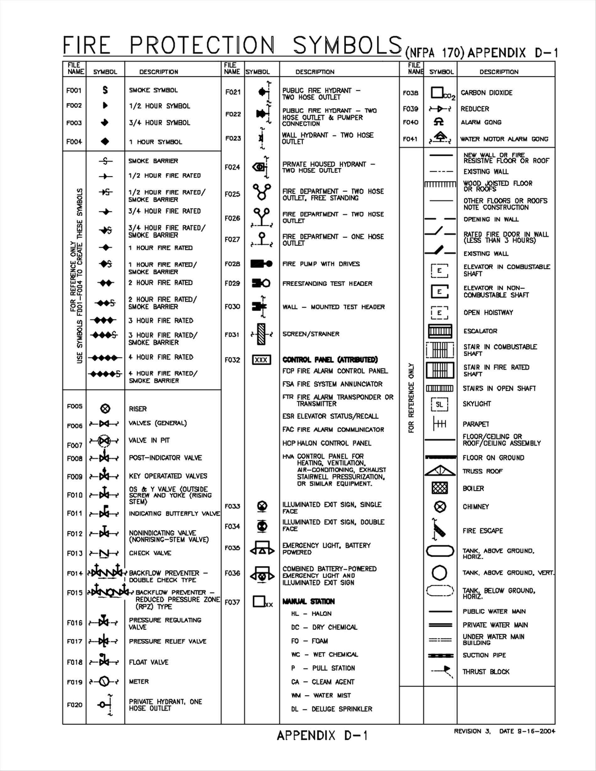
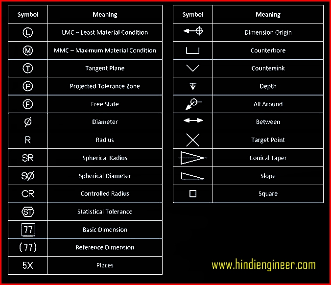
Web electrical symbols and electronic circuit symbols are used for drawing schematic diagram. Click on the links below to learn more about each gd&t symbol or concept, and be sure to download the free wall chart for a quick reference when at your desk or. Web symbols in mechanical drawings are graphical elements accepted by standards and codes. Web various symbols and abbreviations in engineering drawings give you information about the dimensions, design, and materials used. They represent components, elements, details, characteristics, actions, features, and conditions important for a defined technical product or system. In this chapter we will study what constitutes good drafting technique for each line type. Web basic types of symbols used in engineering drawings are countersink, counterbore, spotface, depth, radius, and diameter. Learning to read blueprints can be hard. In construction, every blueprint and drawing is a complex web of information, distilled into symbols and lines that determine the work executed onsite. Web list of drafting symbols.
The symbols represent electrical and electronic components. Web this chapter will introduce the five common categories of drawings. It can find the most similar character shapes for your drawing. Web symbols in mechanical drawings are graphical elements accepted by standards and codes. Below, you’ll find our list of drafting symbols in alphabetical order. They are fundamental to every standardized engineering project, commonly used for the design, installation, and optimization of a system. However, symbols can be meaningful only if they are created according to the relevant standards or conventions. Currently, we have 16 symbols for geometric tolerances, which are categorized according to the tolerance they specify. That’s why we’ve broken down the process into bite size chunks. Engineering drawing symbols are like a secret language that only engineers can decode.

ANSI Standard JSTD710 Architectural Drawing Symbols Bedrock Learning
In the design industry, there are standardized line types and correct techniques to be used for producing professionally hand drafted drawings. Web electrical symbols and electronic circuit symbols are used for drawing schematic diagram. Web drafting symbols symbols provide a “common language” for drafters all over the world. This document describes and illustrates common dimensioning, gd&t, architectural, piping, and electrical.
Drawing Symbols at Explore collection of Drawing
The symbols represent electrical and electronic components. Web various symbols and abbreviations in engineering drawings give you information about the dimensions, design, and materials used. These symbols carry specific meanings and convey vital information about various facets of a design. They represent components, elements, details, characteristics, actions, features, and conditions important for a defined technical product or system. Web drafting.

Mechanical Engineering Drawing Symbols Pdf Free Download at
They are 1) piping and instrument drawings (p&ids), 2) electrical single lines and schematics, 3) electronic diagrams and schematics, 4) logic diagrams and prints, and 5) fabrication, construction, and architectural drawings. Web symbols in mechanical drawings are graphical elements accepted by standards and codes. This list includes abbreviations common to the vocabulary of people who work with engineering drawings in.

Mechanical Engineering Drawing Symbols Pdf Free Download at
With shapecatcher.com you can search through a database of characters by simply drawing your character into a box. It is the size that the tolerance envelope is based on. That’s why we’ve broken down the process into bite size chunks. These symbols carry specific meanings and convey vital information about various facets of a design. The aptly named symbols.com is.
Standard Engineering Drawing Symbols
It is the size that the tolerance envelope is based on. The following are definitions commonly used throughout industry when discussing gd&t or composing engineering drawing notes. In this chapter we will study what constitutes good drafting technique for each line type. Many of the definitions are not official asme, ansi or iso terminology. They are 1) piping and instrument.

Civil Engineering Drawing Symbols And Their Meanings at PaintingValley
Currently, we have 16 symbols for geometric tolerances, which are categorized according to the tolerance they specify. Engineering drawing symbols are like a secret language that only engineers can decode. [1] these symbols and abbreviations are standardized by the american national standards institute (asmi) and the american society of mechanical engineers (asme) in the us. Mep (mechanical, electrical, and plumbing).

Engineering Drawing Symbols And Their Meanings Pdf at PaintingValley
You can also check out the gd&t symbols and terms on our site. They represent components, elements, details, characteristics, actions, features, and conditions important for a defined technical product or system. The symbols represent electrical and electronic components. Currently, we have 16 symbols for geometric tolerances, which are categorized according to the tolerance they specify. Web find common gd&t symbols.

Important Concept 14+ CAD Drawing Symbols
Engineering drawing symbols are like a secret language that only engineers can decode. Currently, we have 16 symbols for geometric tolerances, which are categorized according to the tolerance they specify. They are fundamental to every standardized engineering project, commonly used for the design, installation, and optimization of a system. Web engineering drawing abbreviations and symbols are used to communicate and.

M&e Drawing Symbols Back To Basics Komseq
The following are definitions commonly used throughout industry when discussing gd&t or composing engineering drawing notes. The following is a short list of symbols that normally appear on a technical drawing and need understanding. The aptly named symbols.com is a great place to start your symbol search. Web symbols in mechanical drawings are graphical elements accepted by standards and codes..

Standard Engineering Drawing Symbols
Just type in a query at the top, and you'll see symbols that match it. Currently, we have 16 symbols for geometric tolerances, which are categorized according to the tolerance they specify. You can also check out the gd&t symbols and terms on our site. They represent components, elements, details, characteristics, actions, features, and conditions important for a defined technical.
Web You Need To Find A Specific Unicode Character?
In the example shown, 24 is the nominal size. That’s why we’ve broken down the process into bite size chunks. Mep (mechanical, electrical, and plumbing) a. The symbols represent electrical and electronic components.
Learning To Read Blueprints Can Be Hard.
Web symbols in mechanical drawings are graphical elements accepted by standards and codes. Web various symbols and abbreviations in engineering drawings give you information about the dimensions, design, and materials used. In this chapter we will study what constitutes good drafting technique for each line type. Web may 5, 2022 by brandon fowler.
The Following Is A Short List Of Symbols That Normally Appear On A Technical Drawing And Need Understanding.
Engineering drawing symbols are like a secret language that only engineers can decode. Web a convenient guide for geometric dimensioning and tolerancing (gd&t) symbols at your fingertips. It is the size that the tolerance envelope is based on. They are 1) piping and instrument drawings (p&ids), 2) electrical single lines and schematics, 3) electronic diagrams and schematics, 4) logic diagrams and prints, and 5) fabrication, construction, and architectural drawings.
In Construction, Every Blueprint And Drawing Is A Complex Web Of Information, Distilled Into Symbols And Lines That Determine The Work Executed Onsite.
Unlike a model, engineering drawings offer more specific detail and requirements, such as: Just type in a query at the top, and you'll see symbols that match it. Web a piping and instrumentation diagram (drawing) is a graphical representation of an engineering process system. Web list of drafting symbols.