Engineered Drawings
Engineered Drawings - Web engineering drawing basics explained. This is even truer for engineers and machinists. Engineering drawings use standardised language and symbols. This list includes abbreviations common to the vocabulary of people who work with engineering drawings in the manufacture and inspection of parts and assemblies. Web engineering drawings are used to communicate design conceptsand design intent using a standardized pictorial language comprised of lines, shapes, and symbols. It’s an essential skill that translates complex ideas and theoretical designs into visual blueprints. Creating drawings using the cad software is a straightforward process; Drawings and pictures are among the best means of communicating one’s ideas and views. Web an engineering drawing is a subcategory of technical drawings that show the shape, structure, dimensions, tolerances, accuracy and other requirements needed to manufacture a product or part. Web unlike a 3d model, an engineering drawing offers a lot more specific information and requirements, including:
[4] the name and contact information for the company producing or distributing the part. Make a the lowest point of the drawing. Web engineering drawing is a specialized form of communication that uses a strict set of symbols, standards, and perspectives to depict mechanical, electrical, or structural designs. Web by definition, a technical drawing—also known as an engineering drawing—is a detailed, precise diagram or plan that conveys information about how an object functions or is constructed. Civil engineering drawings are the bedrock of any construction project, acting as the visual roadmap that guides engineers, architects, and construction teams toward successful project completion. The top cad programs provide an array of precision tools to ensure that every line, curve, and angle is exact. Do not dimension the drawing. General notes in engineering drawing commonly consist of a set of standard notes or instructions, specific client specifications used when. Engineering drawing, often referred to as technical or mechanical drawing, is the universal language of engineers and technicians. Web drawing description remarks;
This is so easily overlooked, but may convey very important information and instructions to the person reading the drawing. Engineering drawings use standardised language and symbols. Web engineering working drawings basics. Smartdraw gives you the power to create engineering drawings of all kinds more easily and more affordably than any other engineering design software on the market. Learn the ins and outs of engineering drawing standards, such as iso and ansi, which govern the symbols, abbreviations, and notations used in. Web engineering drawing abbreviations and symbols are used to communicate and detail the characteristics of an engineering drawing. The video below covers the fundamentals, including the different types of views, first and third angle projection methods, dimensioning, tolerancing, best practices when creating drawings. Web unlike a 3d model, an engineering drawing offers a lot more specific information and requirements, including: Protected endwalls for round & oval pipes (pipe sizes 18” to 72”, all skews, 2:1 & 3:1 slopes) for endwall dimension labeling Web engineering drawings are a collection of standardized language, symbols, and graphic patterns to convey all the information needed to manufacture a product or part.
Download How To Read Basic Engineering Drawing Guide Pictures
Web drawing description remarks; A dimension listed on an engineering drawing is known as the _______ _______. Technical standards exist to provide glossaries of. Smartdraw gives you the power to create engineering drawings of all kinds more easily and more affordably than any other engineering design software on the market. Creating drawings using the cad software is a straightforward process;
Engineering Drawing Symbols And Their Meanings Pdf at GetDrawings
[4] the name and contact information for the company producing or distributing the part. Civil engineering drawings are the bedrock of any construction project, acting as the visual roadmap that guides engineers, architects, and construction teams toward successful project completion. The mechanical engineering branch, mechanical systems division, has been delegated Smartdraw gives you the power to create engineering drawings of.

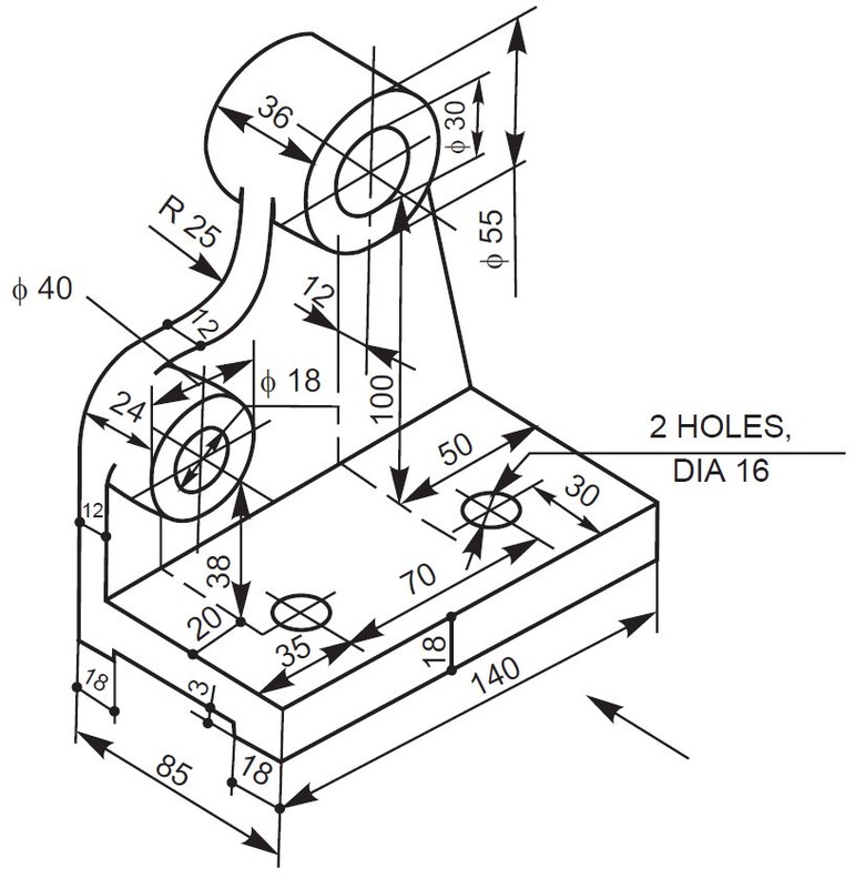
Mechanical Drawing With Dimension
Web an engineering drawing is a subcategory of technical drawings that show the shape, structure, dimensions, tolerances, accuracy and other requirements needed to manufacture a product or part. Drawings and pictures are among the best means of communicating one’s ideas and views. Do not dimension the drawing. 3d models are good to have and are usually (especially nowadays) used in.

how to read civil engineering drawings Engineering Feed
Protected endwalls for round & oval pipes (pipe sizes 18” to 72”, all skews, 2:1 & 3:1 slopes) for endwall dimension labeling They are a good visual representation of the desired item,. [4] the name and contact information for the company producing or distributing the part. The top cad programs provide an array of precision tools to ensure that every.
Engineering Drawing at GetDrawings Free download
Web the best online solution for drawing engineering diagrams. Web some of the most important information on engineering drawings, are general notes. Engineering drawing, often referred to as technical or mechanical drawing, is the universal language of engineers and technicians. Understanding the basics of engineering drawing is a great first step. In that case, the graphic language of the drawing.
Engineering Drawings Justin R. Palmer
An engineering drawing helps to. Web engineering drawing abbreviations and symbols are used to communicate and detail the characteristics of an engineering drawing. This makes understanding the drawings simple with little to no personal. This will allow you to communicate the. Web engineering working drawings basics.
Engineering Drawing at GetDrawings Free download
An engineering drawing helps to. Usually, a number of drawings are necessary to completely specify even a simple component. Web an engineering drawing is a type of technical drawing that is used to convey information about an object. General notes in engineering drawing commonly consist of a set of standard notes or instructions, specific client specifications used when. Web by.
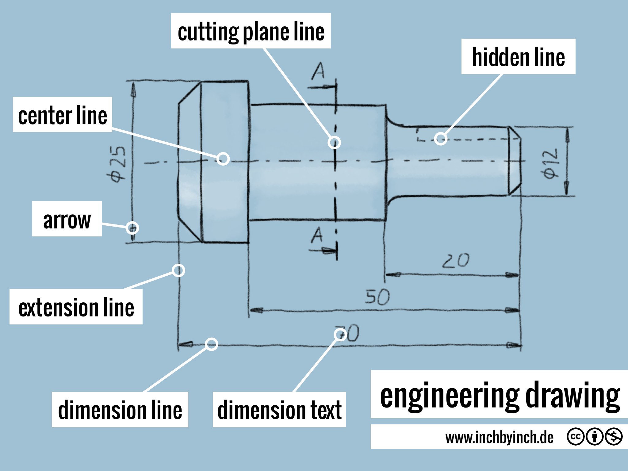
INCH Technical English engineering drawing
These drawings are essentially the blueprints or plans for manufacturing a wide array of products and structures. Technical standards exist to provide glossaries of. Engineering drawings use standardised language and symbols. Do not dimension the drawing. They are a good visual representation of the desired item,.

Mechanical Engineer Drawing at GetDrawings Free download
The mechanical engineering branch, mechanical systems division, has been delegated This will allow you to communicate the. Web 3 precision tools. Smartdraw includes a large collection of templates and mechanical engineering and architectural shapes and. An engineering drawing is a subcategory of technical drawings.

Engineering Drawing A Science or Art RRCE
Web an engineering drawing is a subcategory of technical drawings that show the shape, structure, dimensions, tolerances, accuracy and other requirements needed to manufacture a product or part. In that case, the graphic language of the drawing would help manufacturing engineers align their operations according to the drawing drafted by the cad engineer or a draftsman. If the isometric drawing.
Engineers, Electricians, And Contractors All Use These Drawings As Deliverables And (Often Legally Guarded) Constructable Documents When Constructing Or.
The title block appears either at the top or bottom of an engineering drawing. The purpose is to convey all the information necessary for manufacturing a product or a part. These meticulously crafted blueprints hold the key to turning grand ideas into tangible structures that shape our cities and landscapes. One can pack a great deal of information into an isometric drawing.
General Notes In Engineering Drawing Commonly Consist Of A Set Of Standard Notes Or Instructions, Specific Client Specifications Used When.
Check the title block for basic information about the drawing. Engineering graphics is used in the design process for visualization, communication, and documentation. Import) a 3d model, and then we start inserting the views in the drawing and adding dimensions. They are sophisticated technical drawings that provide details on the geometry, dimensions, materials, and tolerancesof an object.
Read This First To Find Out Crucial Information About The Drawing, Including:
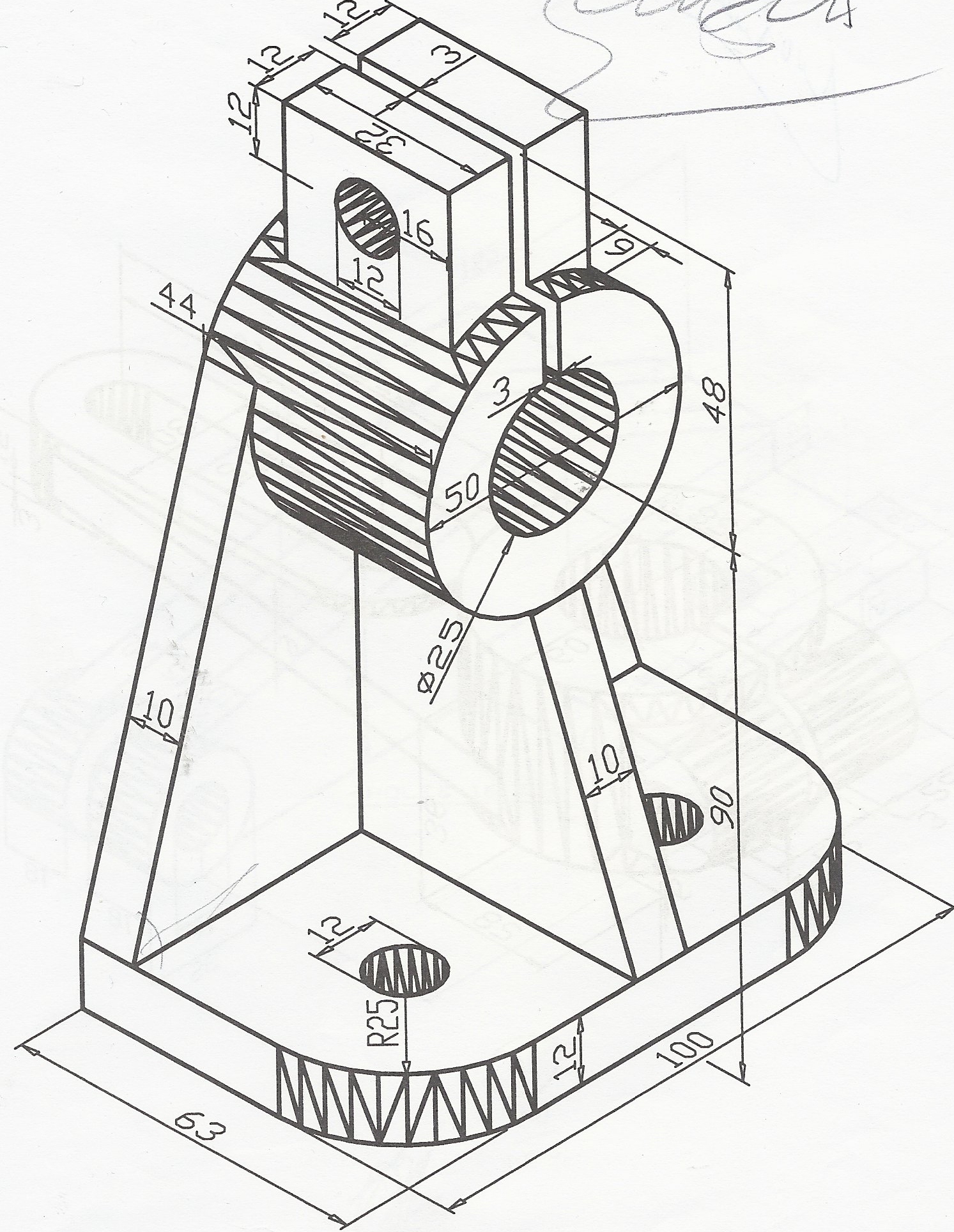
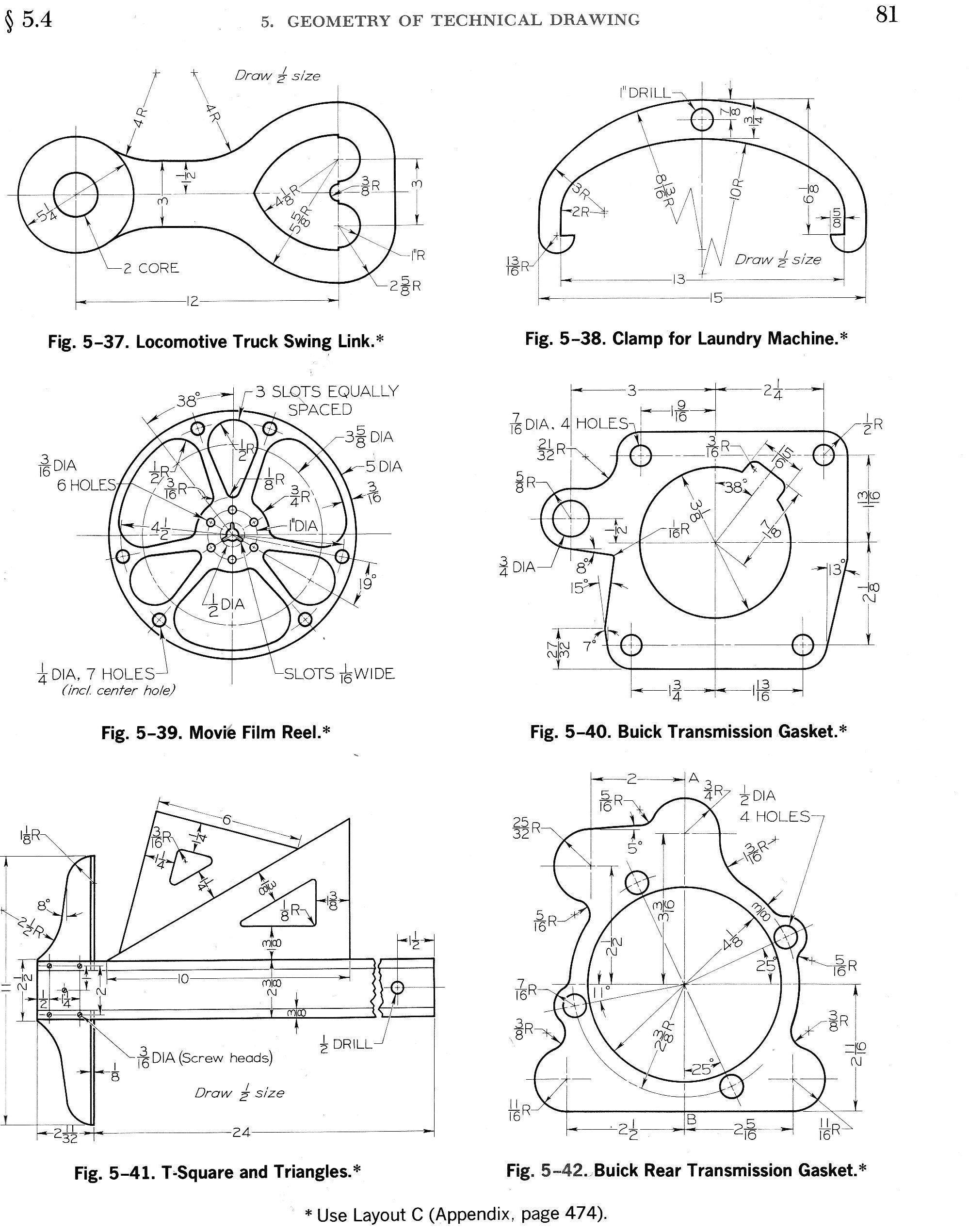
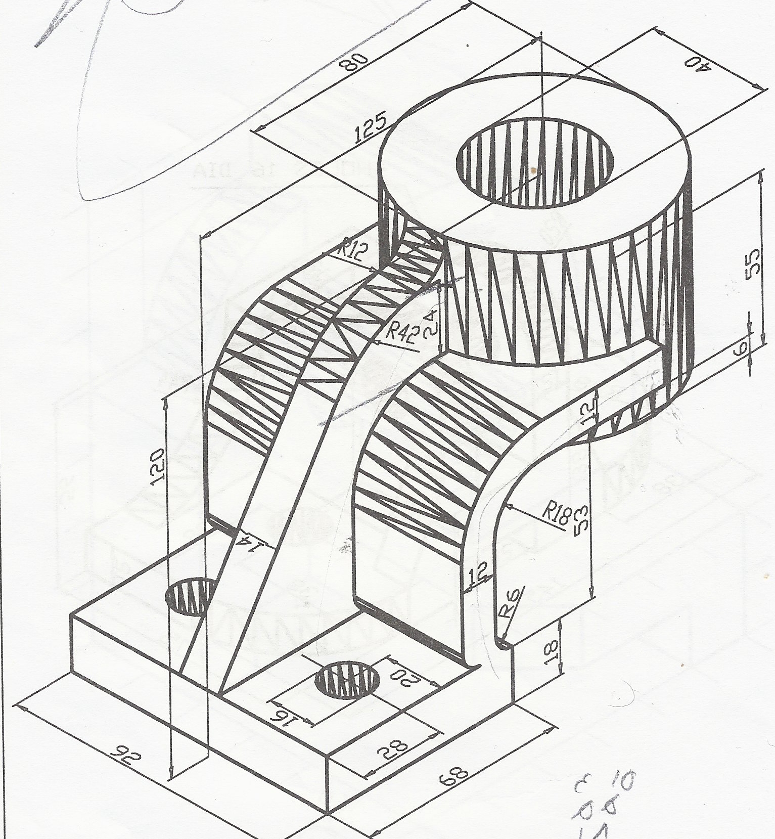
Web task 5.6 convert the orthographic drawing shown below into an isometric drawings. A complete understanding of the object should be possible from the drawing. Web engineering drawing is a specialized form of communication that uses a strict set of symbols, standards, and perspectives to depict mechanical, electrical, or structural designs. This makes understanding the drawings simple with little to no personal.
The Top Cad Programs Provide An Array Of Precision Tools To Ensure That Every Line, Curve, And Angle Is Exact.
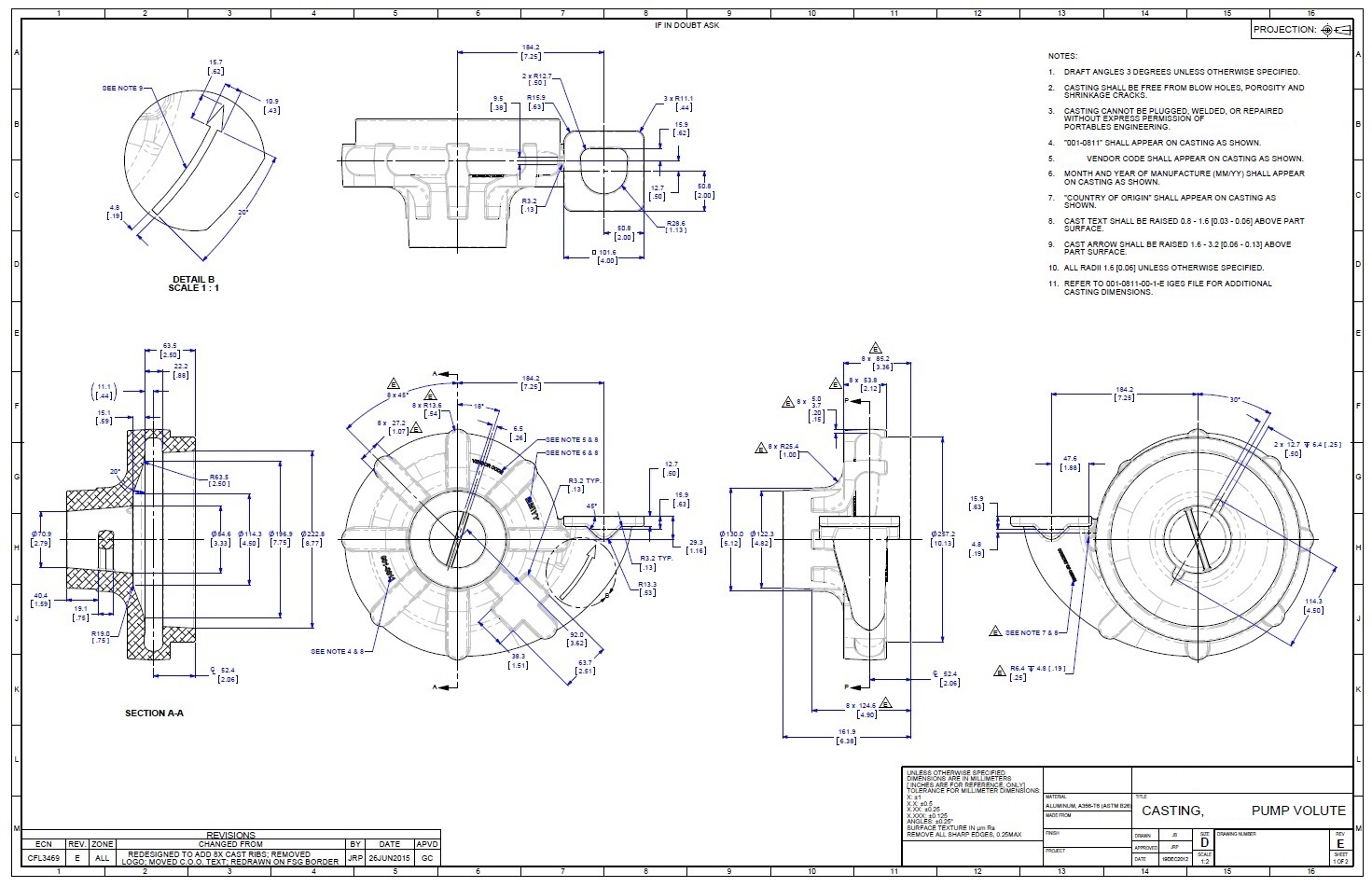
Web although engineers created the engineering drawings in the past by hand, today, they are primarily done in cad software like autodesk fusion 360. Web an engineering drawing is a subcategory of technical drawings that show the shape, structure, dimensions, tolerances, accuracy and other requirements needed to manufacture a product or part. Web the gsfc engineering drawing standards manual is the official source for the requirements and interpretations to be used in the development and presentation of engineering drawings and related documentation for the gsfc. Engineering drawings use standardised language and symbols.