Engineering Drawing Symbols And Meanings
Engineering Drawing Symbols And Meanings - Why abbreviations and symbols are needed for engineering drawing? Web drafting symbols symbols provide a “common language” for drafters all over the world. Web the symbols used for each hole and how they are shown on engineering drawings. Here are more commonly used engineering drawing symbols and design elements as below. This list includes abbreviations common to the vocabulary of people who work with engineering drawings in the manufacture and inspection of parts and assemblies. Asme handles some specific ones related to mechanical engineering. Unlike a model, engineering drawings note much more specific information and requirements, such as: Using abbreviations and symbols allows for concise representation, making the drawings easier to read and understand. Web it establishes symbols, rules, definitions, requirements, defaults, and recommended practices for stating and interpreting gd&t and related requirements for use on engineering drawings, models defined in digital data files, and in related documents. Web gd&t (geometric dimensioning and tolerancing) is a symbolic language used in engineering drawings to communicate design and manufacturing requirements.
Why abbreviations and symbols are needed for engineering drawing? The table shows dimensioning symbols found on engineering and mechanical drawings. However, symbols can be meaningful only if they are created according to the relevant standards or conventions. You can also check out the gd&t symbols and terms on our site. Web the following is a short list of symbols that normally appear on a technical drawing and need understanding. 18 plus years experiencepremium customer service Web gd&t symbol charts for engineering drawing & drafting. Common engineering drawing abbreviations used in cnc machining. Web what are the most commonly used engineering drawing symbols and their meanings? As with other engineering terms, abbreviations and symbols are subject to standardization.
As with other engineering terms, abbreviations and symbols are subject to standardization. Common engineering drawing abbreviations used in cnc machining. Web how to read an engineering drawing symbol. Most symbols have been in y14.5 since at least 1994. Web gd&t symbol charts for engineering drawing & drafting. Dimensioning and tolerancing with 45 elements; How to read symbols in an engineering drawing? How each type of hole is used in engineering. Engineering drawings often contain a large amount of information, including dimensions, tolerances, annotations, and other details. Here are more commonly used engineering drawing symbols and design elements as below.

Civil Engineering Drawing Symbols And Their Meanings at PaintingValley
Dimensioning and tolerancing with 45 elements; How to read symbols in an engineering drawing? Why abbreviations and symbols are needed for engineering drawing? Using abbreviations and symbols allows for concise representation, making the drawings easier to read and understand. Web the symbols used for each hole and how they are shown on engineering drawings.

Engineering Drawing Symbols And Their Meanings Pdf at PaintingValley
Here are more commonly used engineering drawing symbols and design elements as below. Web are engineering drawing abbreviations and symbols standardized? Standard symbols for mechanical components. Web the following is a short list of symbols that normally appear on a technical drawing and need understanding. The first tool in your engineering drawing toolbox is the drawing view.

Engineering Drawing Symbols And Their Meanings Pdf at GetDrawings
However, symbols can be meaningful only if they are created according to the relevant standards or conventions. How each type of hole is used in engineering. We offer you our tips which we believe are useful for dispelling uncertainty by comparing the symbol with its graphic representation. Web it establishes symbols, rules, definitions, requirements, defaults, and recommended practices for stating.

How To Read Architectural Drawings Symbols The Architect
Web drawings are comprised of symbols and lines that represent components or systems. Web how to read an engineering drawing symbol. The mechanical engineering branch, mechanical systems division, has been delegated Web what are the most commonly used engineering drawing symbols and their meanings? Engineering drawing symbols play a vital role in communication among engineers and other stakeholders involved in.

Engineering Drawing Symbols And Their Meanings Pdf at PaintingValley
Radius can be for the inside and outside curved surface on the part. Web how to read an engineering drawing symbol. Web mechanical drawings, schematics, diagrams, plans, and maps are constructed using special graphical symbols, generally accepted in mechanical engineering. Using abbreviations and symbols allows for concise representation, making the drawings easier to read and understand. Web gd&t symbol charts.

Mechanical Engineering Drawing Symbols Pdf Free Download at
We offer you our tips which we believe are useful for dispelling uncertainty by comparing the symbol with its graphic representation. Web gd&t (geometric dimensioning and tolerancing) is a symbolic language used in engineering drawings to communicate design and manufacturing requirements. Web drafting symbols symbols provide a “common language” for drafters all over the world. Engineering drawing symbols play a.
Engineering Drawing Symbols And Their Meanings Pdf at PaintingValley
The mechanical engineering branch, mechanical systems division, has been delegated Web mechanical drawings, schematics, diagrams, plans, and maps are constructed using special graphical symbols, generally accepted in mechanical engineering. Asme handles some specific ones related to mechanical engineering. Note the comparison with the iso standards. Unlike a model, engineering drawings note much more specific information and requirements, such as:

ANSI Standard JSTD710 Architectural Drawing Symbols Bedrock Learning
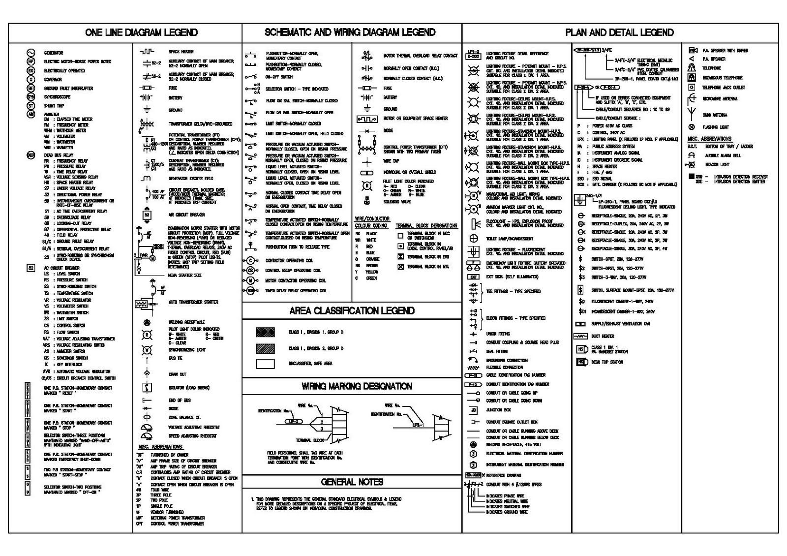
In the united states, the majority of these terms follow norms ansi or asa. They are 1) piping and instrument drawings (p&ids), 2) electrical single lines and schematics, 3) electronic diagrams and schematics, 4) logic diagrams and prints, and 5) fabrication, construction, and architectural drawings. Engineering drawing symbols play a vital role in communication among engineers and other stakeholders involved.

Engineering Drawing Symbols And Their Meanings Pdf at PaintingValley
Unlike a model, engineering drawings note much more specific information and requirements, such as: Web the gsfc engineering drawing standards manual is the official source for the requirements and interpretations to be used in the development and presentation of engineering drawings and related documentation for the gsfc. Work with runsom for your cnc programming projects. Web drafting symbols symbols provide.

Mechanical Engineering Drawing Symbols Pdf Free Download at
Why abbreviations and symbols are needed for engineering drawing? The mechanical engineering branch, mechanical systems division, has been delegated Web are engineering drawing abbreviations and symbols standardized? Unlike a model, engineering drawings note much more specific information and requirements, such as: It includes a set of symbols, text, and tolerances that provide precise information about the size, shape, and orientation.
Engineering Drawing Symbols Play A Vital Role In Communication Among Engineers And Other Stakeholders Involved In The Design And Construction Process.
Most symbols have been in y14.5 since at least 1994. Why abbreviations and symbols are needed for engineering drawing? Web mechanical drawings, schematics, diagrams, plans, and maps are constructed using special graphical symbols, generally accepted in mechanical engineering. How each type of hole is used in engineering.
Asme Handles Some Specific Ones Related To Mechanical Engineering.
Work with runsom for your cnc programming projects. Web it establishes symbols, rules, definitions, requirements, defaults, and recommended practices for stating and interpreting gd&t and related requirements for use on engineering drawings, models defined in digital data files, and in related documents. Web the following is a short list of symbols that normally appear on a technical drawing and need understanding. Web engineering drawing abbreviations and symbols are used to communicate and detail the characteristics of an engineering drawing.
We Offer You Our Tips Which We Believe Are Useful For Dispelling Uncertainty By Comparing The Symbol With Its Graphic Representation.
How to read symbols in an engineering drawing? Web are engineering drawing abbreviations and symbols standardized? Web gd&t (geometric dimensioning and tolerancing) is a symbolic language used in engineering drawings to communicate design and manufacturing requirements. Click on the links below to learn more about each gd&t symbol or concept, and be sure to download the free wall chart for a quick reference when at your desk or.
In The United States, The Majority Of These Terms Follow Norms Ansi Or Asa.
Web engineering drawing abbreviations and symbols are used to communicate and detail the characteristics of an engineering drawing. Web engineering drawing symbols are simple to pick up and use once you understand how to read them. Radius can be for the inside and outside curved surface on the part. Dimensioning and tolerancing with 45 elements;