Engineering Drawing Symbols
Engineering Drawing Symbols - You can also check out the gd&t symbols and terms on our site. Many of the definitions are not official asme, ansi or iso terminology. Web basic types of symbols used in engineering drawings are countersink, counterbore, spotface, depth, radius, and diameter. Web the purpose of this guide is to give you the basics of engineering sketching and drawing. Web the gsfc engineering drawing standards manual is the official source for the requirements and interpretations to be used in the development and presentation of engineering drawings and related documentation for the gsfc. An engineering (or technical) drawing is a graphical representation of a part, assembly, system, or structure and it can be produced using freehand, mechanical tools, or computer methods. Web how to read an engineering drawing symbol. We will treat “sketching” and “drawing” as one. This list includes abbreviations common to the vocabulary of people who work with engineering drawings in the manufacture and inspection of parts and assemblies. Here are more commonly used engineering drawing symbols and design elements as below.
Web it establishes symbols, rules, definitions, requirements, defaults, and recommended practices for stating and interpreting gd&t and related requirements for use on engineering drawings, models defined in digital data files, and in related documents. Web how to read an engineering drawing symbol. We will treat “sketching” and “drawing” as one. Web a convenient guide for geometric dimensioning and tolerancing (gd&t) symbols at your fingertips. Web basic types of symbols used in engineering drawings are countersink, counterbore, spotface, depth, radius, and diameter. Click on the links below to learn more about each gd&t symbol or concept, and be sure to download the free wall chart for a quick reference when at. Any needed height h 2 h h 2 h 60° 2 h identification letter datum feature symbol datum target symbol target point and. Web the purpose of this guide is to give you the basics of engineering sketching and drawing. An engineering (or technical) drawing is a graphical representation of a part, assembly, system, or structure and it can be produced using freehand, mechanical tools, or computer methods. Web every phase of engineering design starting from concept illustration all the way to the manufacturing phase.
Web how to read an engineering drawing symbol. Web the gsfc engineering drawing standards manual is the official source for the requirements and interpretations to be used in the development and presentation of engineering drawings and related documentation for the gsfc. The mechanical engineering branch, mechanical systems division, has been delegated Unlike a model, engineering drawings offer more specific detail and requirements, such as: “sketching” generally means freehand drawing. Web geometric dimensioning and tolerancing symbols you can either create your own library of gd&t symbols, or use one of autocad’s gd&t fonts to insert the symbols as text. Web a convenient guide for geometric dimensioning and tolerancing (gd&t) symbols at your fingertips. Web the purpose of this guide is to give you the basics of engineering sketching and drawing. The following tables show how to construct the symbols. Web it establishes symbols, rules, definitions, requirements, defaults, and recommended practices for stating and interpreting gd&t and related requirements for use on engineering drawings, models defined in digital data files, and in related documents.

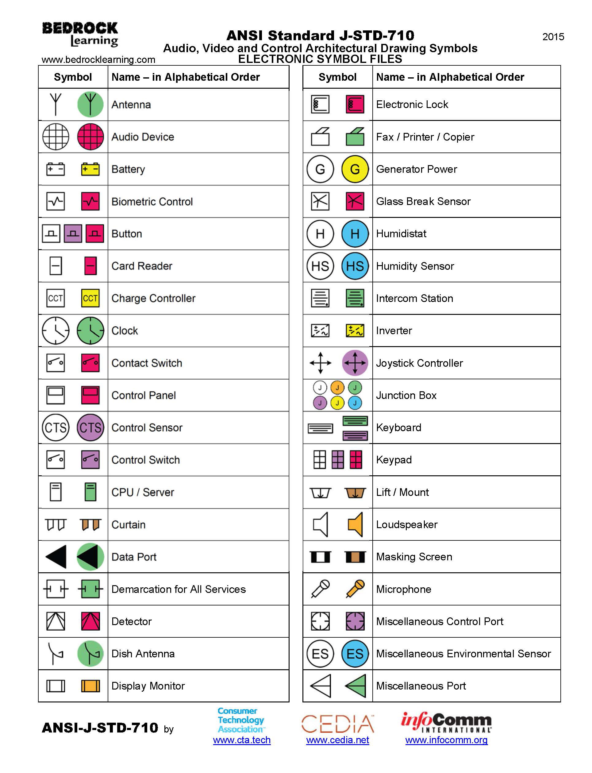
ANSI Standard JSTD710 Architectural Drawing Symbols Bedrock Learning
Web a convenient guide for geometric dimensioning and tolerancing (gd&t) symbols at your fingertips. Web engineering drawing abbreviations and symbols are used to communicate and detail the characteristics of an engineering drawing. Web the following are definitions commonly used throughout industry when discussing gd&t or composing engineering drawing notes. The mechanical engineering branch, mechanical systems division, has been delegated Web.

Engineering Drawing Symbols And Their Meanings Pdf at PaintingValley
Web the purpose of this guide is to give you the basics of engineering sketching and drawing. Web engineering drawing abbreviations and symbols are used to communicate and detail the characteristics of an engineering drawing. Web a convenient guide for geometric dimensioning and tolerancing (gd&t) symbols at your fingertips. Click on the links below to learn more about each gd&t.

Engineering Drawing Symbols And Their Meanings Pdf at PaintingValley
Web a convenient guide for geometric dimensioning and tolerancing (gd&t) symbols at your fingertips. Web geometric dimensioning and tolerancing symbols you can either create your own library of gd&t symbols, or use one of autocad’s gd&t fonts to insert the symbols as text. Web it establishes symbols, rules, definitions, requirements, defaults, and recommended practices for stating and interpreting gd&t and.

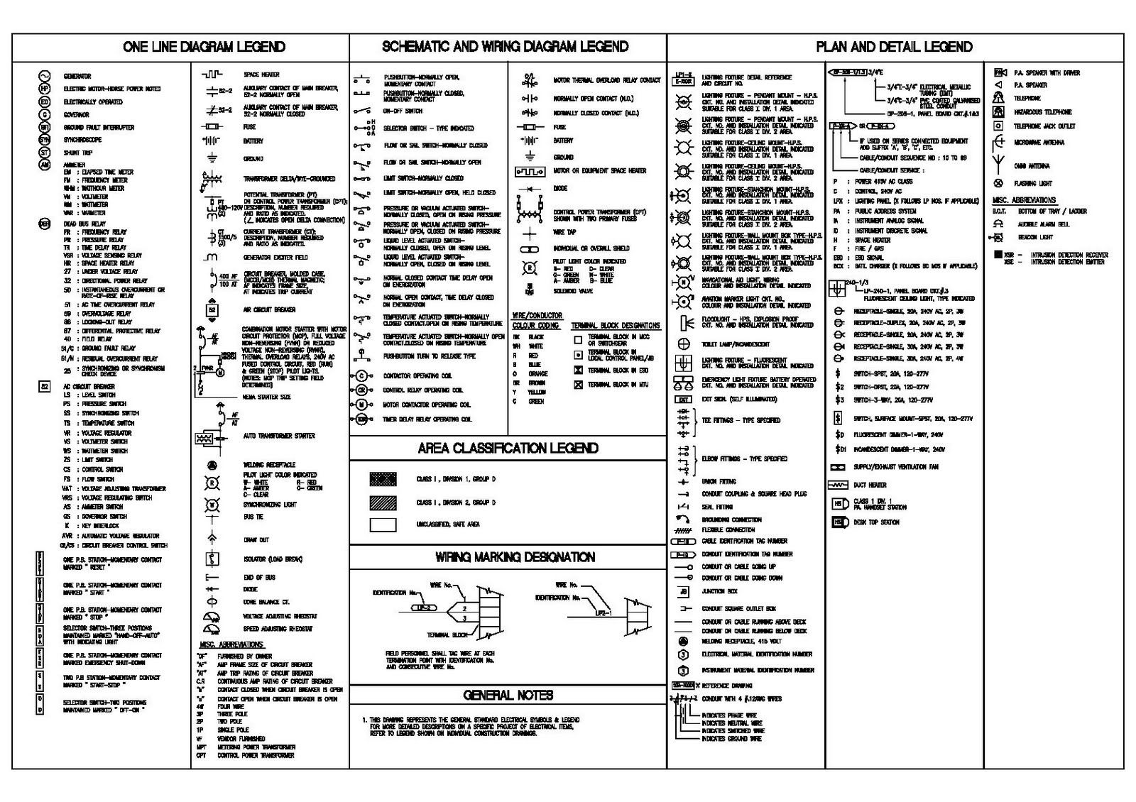
M&e Drawing Symbols Back To Basics Komseq
Web engineering drawing abbreviations and symbols are used to communicate and detail the characteristics of an engineering drawing. Click on the links below to learn more about each gd&t symbol or concept, and be sure to download the free wall chart for a quick reference when at. Many of the definitions are not official asme, ansi or iso terminology. An.

Mechanical Engineering Drawing Symbols Pdf Free Download at
This list includes abbreviations common to the vocabulary of people who work with engineering drawings in the manufacture and inspection of parts and assemblies. The following tables show how to construct the symbols. The mechanical engineering branch, mechanical systems division, has been delegated Web a convenient guide for geometric dimensioning and tolerancing (gd&t) symbols at your fingertips. “sketching” generally means.
Architectural Drawing Symbols Free Download at GetDrawings Free download
Web basic types of symbols used in engineering drawings are countersink, counterbore, spotface, depth, radius, and diameter. We will treat “sketching” and “drawing” as one. An engineering (or technical) drawing is a graphical representation of a part, assembly, system, or structure and it can be produced using freehand, mechanical tools, or computer methods. Any needed height h 2 h h.

Civil Engineering Drawing Symbols And Their Meanings at PaintingValley
Web basic types of symbols used in engineering drawings are countersink, counterbore, spotface, depth, radius, and diameter. The following tables show how to construct the symbols. Web the purpose of this guide is to give you the basics of engineering sketching and drawing. Web every phase of engineering design starting from concept illustration all the way to the manufacturing phase..

Mechanical Engineering Drawing Symbols Pdf Free Download at
Click on the links below to learn more about each gd&t symbol or concept, and be sure to download the free wall chart for a quick reference when at. This list includes abbreviations common to the vocabulary of people who work with engineering drawings in the manufacture and inspection of parts and assemblies. The mechanical engineering branch, mechanical systems division,.
Engineering Drawing Symbols And Their Meanings Pdf at PaintingValley
This list includes abbreviations common to the vocabulary of people who work with engineering drawings in the manufacture and inspection of parts and assemblies. Web engineering drawing abbreviations and symbols are used to communicate and detail the characteristics of an engineering drawing. Web how to read an engineering drawing symbol. You can also check out the gd&t symbols and terms.

Engineering Drawing Symbols And Their Meanings Pdf at PaintingValley
Web every phase of engineering design starting from concept illustration all the way to the manufacturing phase. Web geometric dimensioning and tolerancing symbols you can either create your own library of gd&t symbols, or use one of autocad’s gd&t fonts to insert the symbols as text. Web basic types of symbols used in engineering drawings are countersink, counterbore, spotface, depth,.
The Mechanical Engineering Branch, Mechanical Systems Division, Has Been Delegated
An engineering (or technical) drawing is a graphical representation of a part, assembly, system, or structure and it can be produced using freehand, mechanical tools, or computer methods. “sketching” generally means freehand drawing. Web geometric dimensioning and tolerancing symbols you can either create your own library of gd&t symbols, or use one of autocad’s gd&t fonts to insert the symbols as text. Any needed height h 2 h h 2 h 60° 2 h identification letter datum feature symbol datum target symbol target point and.
This List Includes Abbreviations Common To The Vocabulary Of People Who Work With Engineering Drawings In The Manufacture And Inspection Of Parts And Assemblies.
Web basic types of symbols used in engineering drawings are countersink, counterbore, spotface, depth, radius, and diameter. You can also check out the gd&t symbols and terms on our site. Web every phase of engineering design starting from concept illustration all the way to the manufacturing phase. Web the gsfc engineering drawing standards manual is the official source for the requirements and interpretations to be used in the development and presentation of engineering drawings and related documentation for the gsfc.
Web How To Read An Engineering Drawing Symbol.
We will treat “sketching” and “drawing” as one. Many of the definitions are not official asme, ansi or iso terminology. Web engineering drawing abbreviations and symbols are used to communicate and detail the characteristics of an engineering drawing. Here are more commonly used engineering drawing symbols and design elements as below.
Web The Purpose Of This Guide Is To Give You The Basics Of Engineering Sketching And Drawing.
Web a convenient guide for geometric dimensioning and tolerancing (gd&t) symbols at your fingertips. The following tables show how to construct the symbols. Web it establishes symbols, rules, definitions, requirements, defaults, and recommended practices for stating and interpreting gd&t and related requirements for use on engineering drawings, models defined in digital data files, and in related documents. Unlike a model, engineering drawings offer more specific detail and requirements, such as: