Engineering Drawings Symbols
Engineering Drawings Symbols - Web a wide range of symbols are used to create engineering drawings. This list includes abbreviations common to the vocabulary of people who work with engineering drawings in the manufacture and inspection of parts and assemblies. The asme y14.5 standard establishes symbols, definitions, and rules for geometric dimensioning and tolerancing. Currently, we have 16 symbols for geometric tolerances, which are categorized according to the tolerance they specify. Engineering graphics is used in the design process for visualization, communication, and documentation. Before this method was developed, long and often confusing notes were used to describe part features. Because there is no large space on a drawing to contain all the text to illustrate the image, abbreviations, and symbols are often used in engineering drawings to communicate the characteristics of the product to be. (360 deg) of the part on a datum axis. For example, engineering symbols are used in technical drawings to convey the specific geometry and other details about pieces of equipment or components. However, if the object in figure 2 had a hole on the back.
Web engineering working drawings basics. Web gd&t flatness is a common symbol that references how flat a surface is regardless of any other datum’s or features. For example, engineering symbols are used in technical drawings to convey the specific geometry and other details about pieces of equipment or components. Web the gsfc engineering drawing standards manual is the official source for the requirements and interpretations to be used in the development and presentation of engineering drawings and related documentation for the gsfc. The asme y14.5 standard establishes symbols, definitions, and rules for geometric dimensioning and tolerancing. A generic engineering drawing can be divided into the following five major areas or parts. However, if the object in figure 2 had a hole on the back. This list includes abbreviations common to the vocabulary of people who work with engineering drawings in the manufacture and inspection of parts and assemblies. Often models are used in conjunction with engineering drawings to show a good visual representation. Learn the ins and outs of engineering drawing standards, such as iso and ansi, which govern the symbols, abbreviations, and notations used in.
(360 deg) of the part on a datum axis. But before learning how to read the actual drawing, an understanding of the. Web geometric dimensioning and tolerancing, gd&t symbols, gd&t training definitions, symbols. Web engineering drawing abbreviations and symbols are used to communicate and detail the characteristics of an engineering drawing. Web gd&t drawings and symbols. The mechanical engineering branch, mechanical systems division, has been delegated One can pack a great deal of information into an isometric drawing. Before this method was developed, long and often confusing notes were used to describe part features. A generic engineering drawing can be divided into the following five major areas or parts. Web engineering working drawings basics.

Mechanical Engineering Drawing Symbols Pdf Free Download at
Before this method was developed, long and often confusing notes were used to describe part features. Web asme y14.5 is an established, widely used gd&t standard containing all the necessary information for a comprehensive gd&t system. Web there are literally hundreds of engineering drawing symbols and they’re used in a variety of ways. They are a good visual representation of.

Engineering Drawing Symbols And Their Meanings Pdf at PaintingValley
Before this method was developed, long and often confusing notes were used to describe part features. Currently, we have 16 symbols for geometric tolerances, which are categorized according to the tolerance they specify. Classification and symbols of geometric tolerance characteristics. Web gd&t flatness is a common symbol that references how flat a surface is regardless of any other datum’s or.

Engineering Drawing Symbols And Their Meanings Pdf at PaintingValley
Web any engineering drawing should show everything: Web familiar with the standard conventions, rules, and basic symbols used on the various types of drawings. A generic engineering drawing can be divided into the following five major areas or parts. Web engineering drawing abbreviations and symbols are used to communicate and detail the characteristics of an engineering drawing. Currently, we have.
Architectural Drawing Symbols Free Download at GetDrawings Free download
An engineering drawing is a type of technical drawing that is used to convey information about an object. Usually, a number of drawings are necessary to completely specify even a simple component. Engineering graphics is used in the design process for visualization, communication, and documentation. Web gd&t flatness is a common symbol that references how flat a surface is regardless.

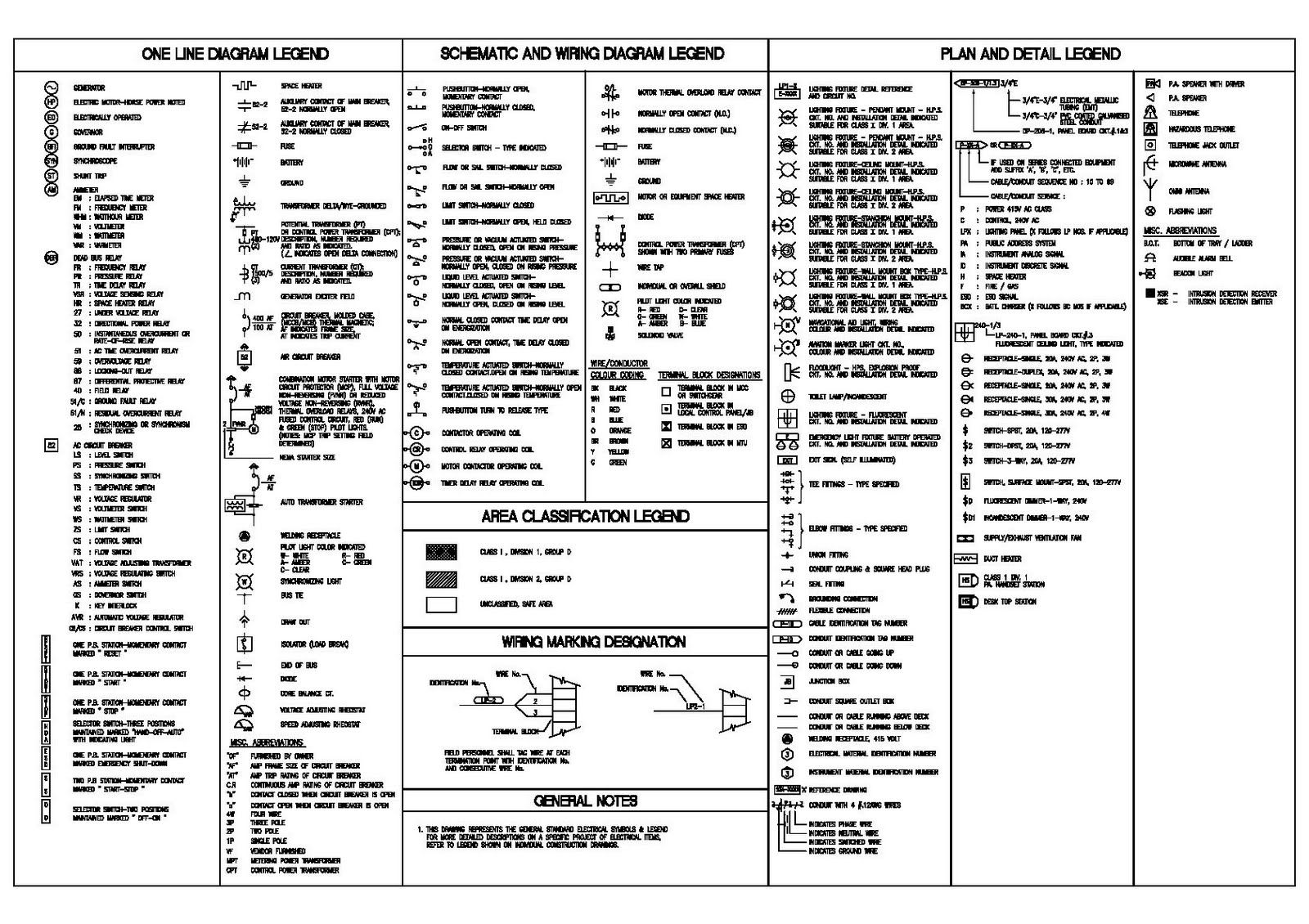
M&e Drawing Symbols Back To Basics Komseq
Learn the ins and outs of engineering drawing standards, such as iso and ansi, which govern the symbols, abbreviations, and notations used in. Web the gsfc engineering drawing standards manual is the official source for the requirements and interpretations to be used in the development and presentation of engineering drawings and related documentation for the gsfc. To read and understand.

Civil Engineering Drawing Symbols And Their Meanings at PaintingValley
Learn the ins and outs of engineering drawing standards, such as iso and ansi, which govern the symbols, abbreviations, and notations used in. Read this first to find out crucial information about the drawing, including: Stay in the know with the latest methods, terms, applications, symbols, abbreviations and diagrams. Circular runout is most often specified on an engineering drawing where.

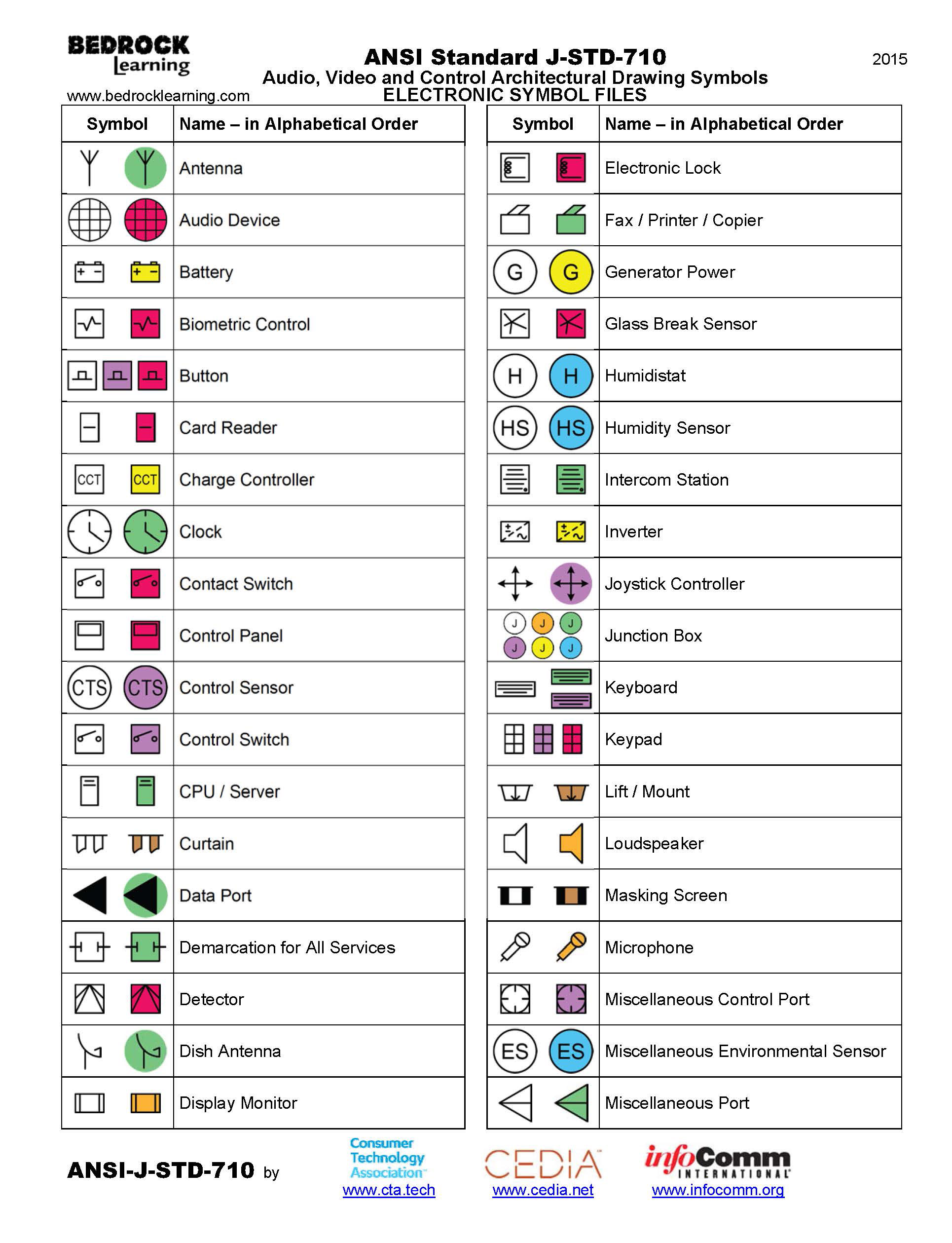
ANSI Standard JSTD710 Architectural Drawing Symbols Bedrock Learning
Web defines the types of engineering drawings most frequently used to establish engineering requirements. The flatness tolerance references two parallel planes (parallel to the surface. To limit errors caused by personal interpretation, engineering drawings and diagrams are. Iso 1101 g&t sumbols and definitions. (360 deg) of the part on a datum axis.

Engineering Drawing Symbols And Their Meanings Pdf at PaintingValley
Note the comparison with the iso standards. Before this method was developed, long and often confusing notes were used to describe part features. An engineering drawing is a type of technical drawing that is used to convey information about an object. After selecting many elements at once, all drawing annotations will move together. Web a good design drawing can indicate.
Engineering Drawing Symbols And Their Meanings Pdf at PaintingValley
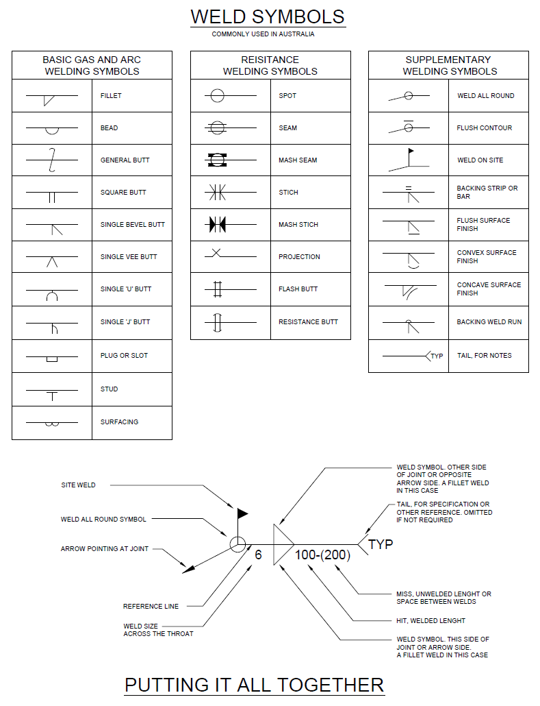
Web the table shows dimensioning symbols found on engineering and mechanical drawings. Web engineering drawing abbreviations and symbols are used to communicate and detail the characteristics of an engineering drawing. Web how to read an engineering drawing symbol. Check the title block for basic information about the drawing. Before this method was developed, long and often confusing notes were used.
Civil Engineering Drawing Symbols And Their Meanings at PaintingValley
Web a good design drawing can indicate all the details needed to produce a mechanical cnc milling part in an easy way. The flatness tolerance references two parallel planes (parallel to the surface. Usually, a number of drawings are necessary to completely specify even a simple component. Often models are used in conjunction with engineering drawings to show a good.
If The Isometric Drawing Can Show All Details And All Dimensions On One Drawing, It Is Ideal.
Web users reported that in inventor drawing, moving text notes with symbol annotation (like sketch symbols or surface symbols) is inconsistent. Web geometric dimensioning and tolerancing, gd&t symbols, gd&t training definitions, symbols. Before this method was developed, long and often confusing notes were used to describe part features. Web the table shows dimensioning symbols found on engineering and mechanical drawings.
It Comes In Useful If A Feature Is To Be Defined On A Drawing That Needs To Be Uniformly Flat Without Tightening Any Other Dimensions On The Drawing.
This list includes abbreviations common to the vocabulary of people who work with engineering drawings in the manufacture and inspection of parts and assemblies. Read this first to find out crucial information about the drawing, including: An engineering drawing is a type of technical drawing that is used to convey information about an object. Web unlike a 3d model, an engineering drawing offers a lot more specific information and requirements, including:
Geometric Tolerances Are Specified Using Symbols On A Drawing.
It describes typical applications and minimum content requirements. To read and understand engineering fluid diagrams and prints, usually referred to as p&ids, an individual must be familiar with the basic symbols. Web asme y14.5 is an established, widely used gd&t standard containing all the necessary information for a comprehensive gd&t system. Web defines the types of engineering drawings most frequently used to establish engineering requirements.
Circular Runout Is Most Often Specified On An Engineering Drawing Where The Referenced Rotates Relative To The Specified Datum Feature.
Note the comparison with the iso standards. 3d models are good to have and are usually (especially nowadays) used in conjunction with drawings. Currently, we have 16 symbols for geometric tolerances, which are categorized according to the tolerance they specify. Web any engineering drawing should show everything: