Engineering Isometric Drawing
Engineering Isometric Drawing - Web to find the length of the edges in the isometric projection: (in making an orthographic projection, any point in the object is mapped onto the drawing by dropping a perpendicular from that point to the plane of the drawing.) an isometric projection results if the plane is oriented so that it makes equal angles (hence “isometric,” or “equal. Web any engineering drawing should show everything: 4.1 shows a cube standing on a corner g (o) with all the faces of the cube are. It is an axonometric projection in which the three coordinate axes appear equally foreshortened and the angle between any two of them is 120 degrees. •isometric drawing is built on 3 main axis namely the vertical axis and two 30 degrees axis from a horizontal line to the left and right of the vertical axis. Make a the lowest point of the drawing. If the isometric drawing can show all details and all dimensions on one drawing, it is ideal. Web an engineering drawing is a type of technical drawing that is used to convey information about an object. Black = object line and hatching;
Web to find the length of the edges in the isometric projection: The different line types are colored for clarity. (in making an orthographic projection, any point in the object is mapped onto the drawing by dropping a perpendicular from that point to the plane of the drawing.) an isometric projection results if the plane is oriented so that it makes equal angles (hence “isometric,” or “equal. How to make an isometric drawing to make an isometric drawing, start with an. Web learn to draw isometric projections using these simple steps provided. Web the isometric is one class of orthographic projections. If the isometric drawing can show all details and all dimensions on one drawing, it is ideal. This is due to the fact that the foreshortening of the axes is equal. One can pack a great deal of information into an isometric drawing. Web piping isometric drawing software.
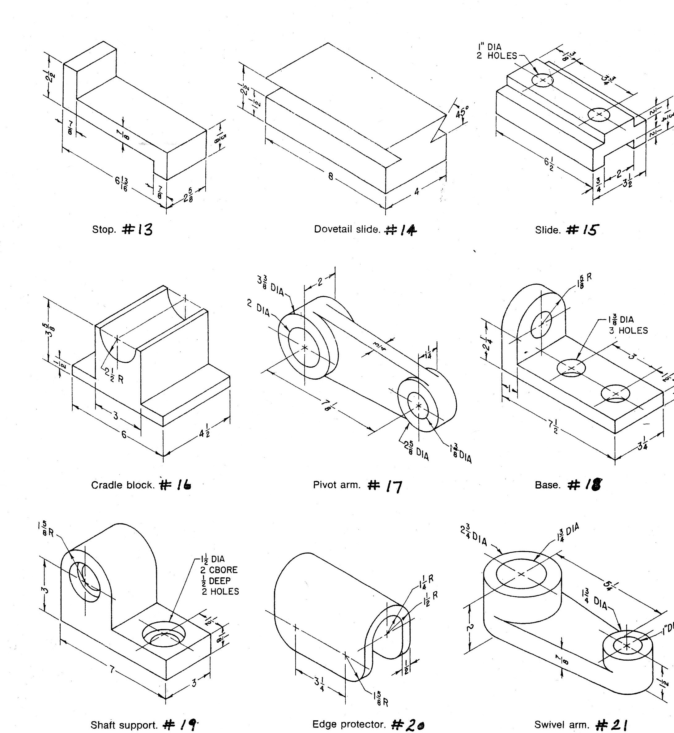
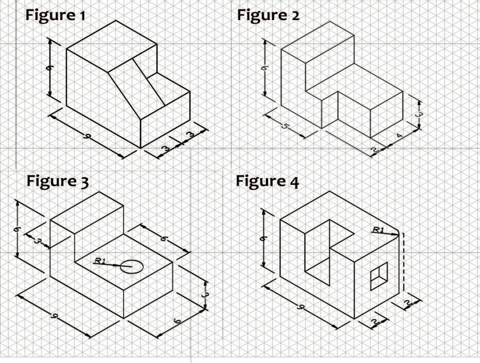
A complete understanding of the object should be possible from the drawing. One can pack a great deal of information into an isometric drawing. It is an axonometric projection in which the three coordinate axes appear equally foreshortened and the angle between any two of them is 120 degrees. This type of drawing is especially useful to engineers because it shows depth, and each line is drawn to scale. One of the defining characteristics of an isometric drawing, compared to other types of 3d representation, is that the final image is not distorted and is always to scale. A complete understanding of the object should be possible from the drawing. Do not dimension the drawing. However, if the object in figure 2 had a hole on the back. Look, for instance, at the Web isometric line is the line that run parallel to any of the isometric axes.
Isometric Drawing at Explore collection of
It is an axonometric projection in which the three coordinate axes appear equally foreshortened and the angle between any two of them is 120 degrees. Click the home tab, and then click the arrow next to the rectangle shape in the tools area, and. One can pack a great deal of information into an isometric drawing. In visio, on the.
What is an Isometric Drawing? Types And Step To Draw
Look, for instance, at the D’c is the actual length of the edge, whereas corresponding edge d’c’ in the. One can pack a great deal of information into an isometric drawing. In visio, on the file menu, click new, and then click basic drawing. These tools generate the 3d representation of the piping layout, including pipe dimensions, fittings, valves, and.
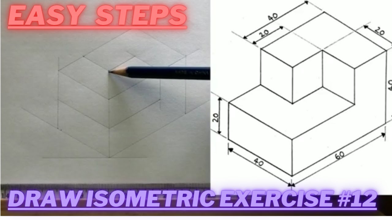
How to draw ISOMETRIC PROJECTIONS Technical Drawing Exercise 12
Web any engineering drawing should show everything: One can pack a great deal of information into an isometric drawing. Do not dimension the drawing. If the isometric drawing can show all details and all dimensions on one drawing, it is ideal. If the isometric drawing can show all details and all dimensions on one drawing, it is ideal.
1.0 Orthographic Sketching Practice Jonesboro High School Engineering
If the isometric drawing can show all details and all dimensions on one drawing, it is ideal. This is due to the fact that the foreshortening of the axes is equal. Web isometric, plan, and elevation presentations are three distinct types of drawings used to depict piping systems in engineering and construction. Isometric drawings are easy once you learn the.
Isometric view drawing example 1 (easy). Links to practice files in
How to make an isometric drawing to make an isometric drawing, start with an. •isometric drawing is built on 3 main axis namely the vertical axis and two 30 degrees axis from a horizontal line to the left and right of the vertical axis. A complete understanding of the object should be possible from the drawing. Web piping isometric drawing.
Isometric Drawing, Projection Its Types, Methods.
A complete understanding of the object should be possible from the drawing. Web piping isometric drawing software. One can pack a great deal of information into an isometric drawing. Isometric drawing, also called isometric. One can pack a great deal of information into an isometric drawing.

Procedure to draw Isometrics ️step by stepbegginersengineering
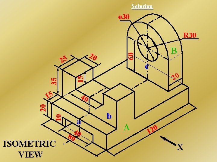
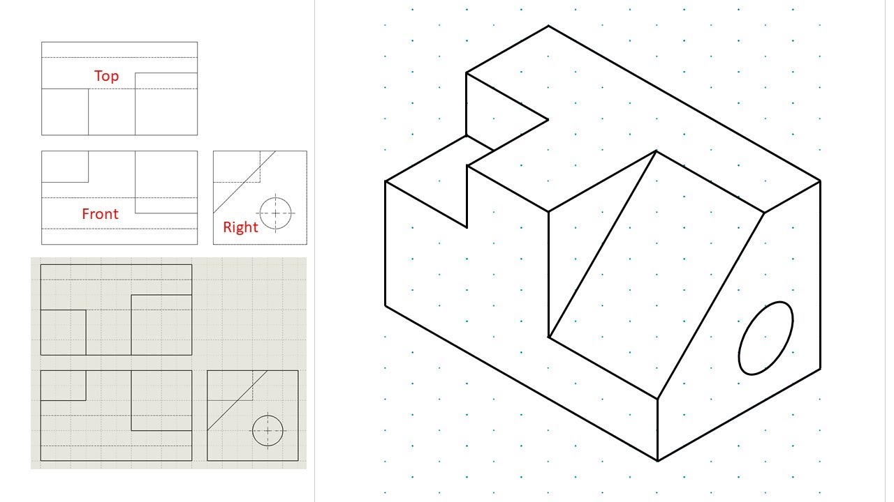
Here is an example of an engineering drawing (an isometric view of the same object is shown above). Web the isometric is one class of orthographic projections. Web welcome back, engineering enthusiasts! Choose between metric units or us units, and click create. If the isometric drawing can show all details and all dimensions on one drawing, it is ideal.

Engineering Drawing Isometric Projections Example 2 YouTube
Web any engineering drawing should show everything: Web to find the length of the edges in the isometric projection: The different line types are colored for clarity. One can pack a great deal of information into an isometric drawing. Any engineering drawing should show everything:
Engineering Drawing Tutorials/Isometric drawing with front and side
One of the defining characteristics of an isometric drawing, compared to other types of 3d representation, is that the final image is not distorted and is always to scale. Web any engineering drawing should show everything: However, if the object in figure 2 had a hole on the back. Black = object line and hatching; Web the isometric is one.
Orthographic Projection from isometric view in Engineering drawing
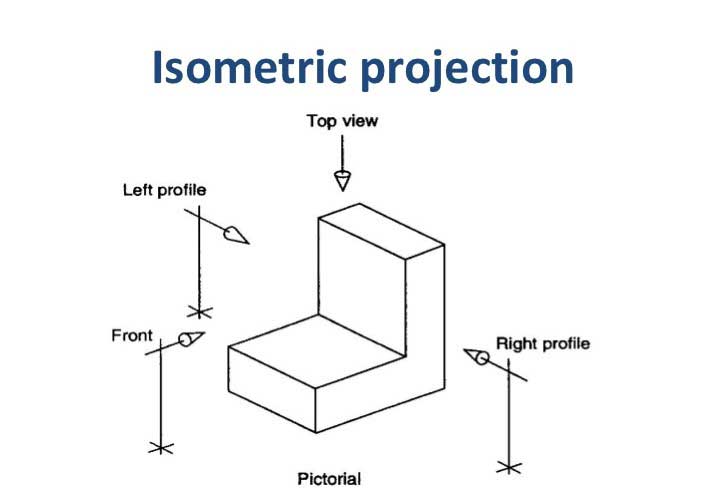
Isometric drawing, also called isometric. A complete understanding of the object should be possible from the drawing. When looking at an isometric drawing, three views are evident. Chapter 4, isometric projections, 4.1 introduction, isometric projection is a type of pictorial projection in which all the three dimensions of the, solid are shown in one view. This type of drawing is.
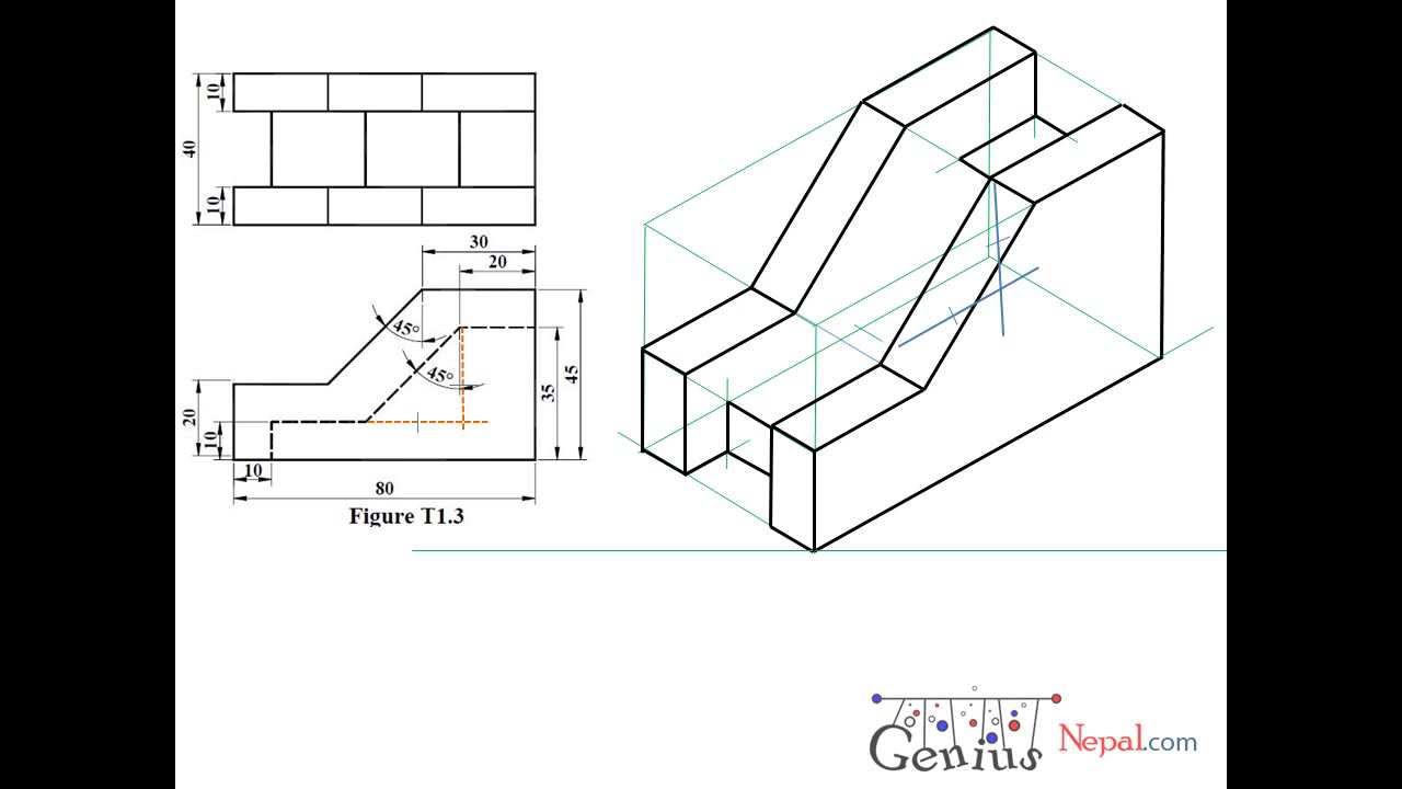
Web Task 5.6 Convert The Orthographic Drawing Shown Below Into An Isometric Drawings.
These drawings are particularly useful for conveying a clear understanding of how different parts of a structure fit together. Web learn to draw isometric projections using these simple steps provided. D’c is the actual length of the edge, whereas corresponding edge d’c’ in the. The different line types are colored for clarity.
However, If The Object In Figure 2 Had A Hole On The Back.
Draw a square d’ab’c od sides equal to the actual length of the edges of the cube with d’b’ as the common diagonal. Piping isometric drawing software is an essential tool for piping engineers and designers to create detailed isometric drawings of piping systems. If the isometric drawing can show all details and all dimensions on one drawing, it is ideal. In visio, on the file menu, click new, and then click basic drawing.
Click The View Tab, And Then Click The Check Box Next To Grid In The Show Area.
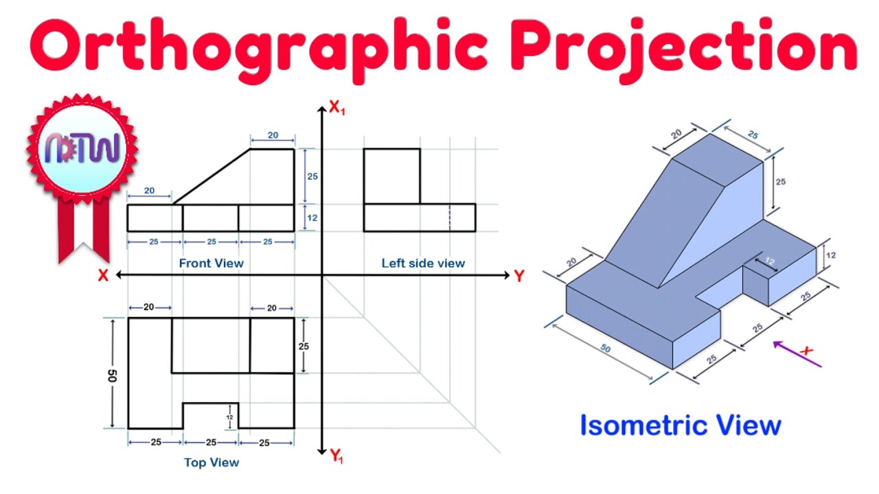
A complete understanding of the object should be possible from the drawing. Web in this video, i have explained how to draw an isometric view of an object from an orthographic view. Web isometric, plan, and elevation presentations are three distinct types of drawings used to depict piping systems in engineering and construction. One can pack a great deal of information into an isometric drawing.
Isometric Drawings Are Easy Once You Learn The Basic Techniques.
Black = object line and hatching; Web an isometric drawing is a 3d representation of an object, room, building or design on a 2d surface. (in making an orthographic projection, any point in the object is mapped onto the drawing by dropping a perpendicular from that point to the plane of the drawing.) an isometric projection results if the plane is oriented so that it makes equal angles (hence “isometric,” or “equal. One of the defining characteristics of an isometric drawing, compared to other types of 3d representation, is that the final image is not distorted and is always to scale.