Hidden Lines In Engineering Drawing
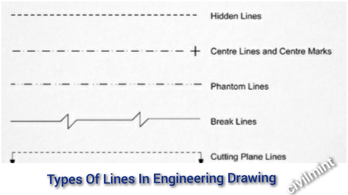
Hidden Lines In Engineering Drawing - These features are typically inside the object or obscured by other surfaces. Centerlines are one of the most frequently used tools in engineering drawing. These types of lines also known as object lines. Web 18.06.2020 by andreas velling. Curved lines (arcs, circles, and ellipses) cutting plane lines. Web there are 12 types of lines usually used in engineering drawing. Cutting plane lines are used in section drawings to show the locations of cutting planes. Web when multiple edges project to the same line on the drawing, the line type is determined by the following precedence: Recognizing such dashed lines while parsing drawings is reasonably straightforward if they are outlined with a ruler and compass but becomes challenging when they are hand. 28k views 9 years ago.
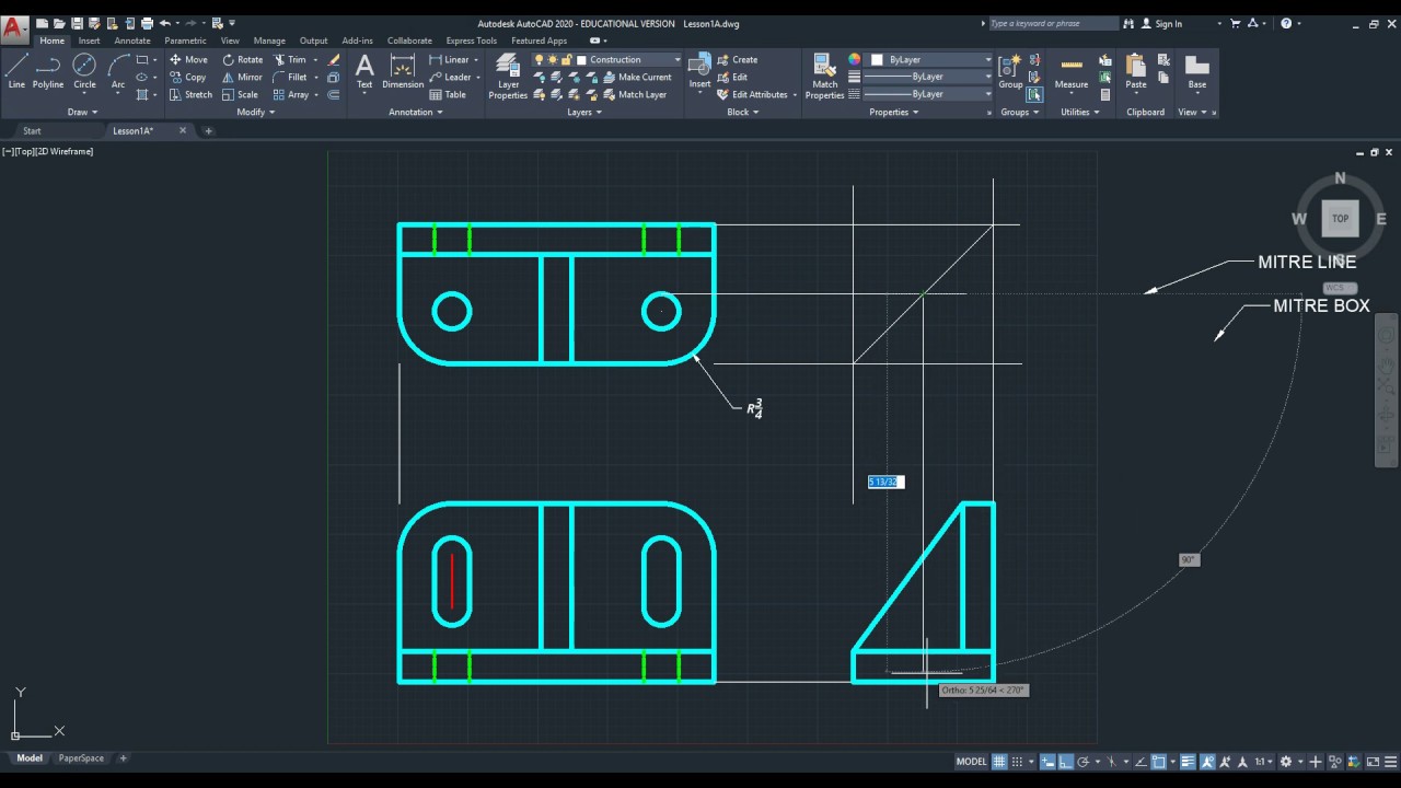
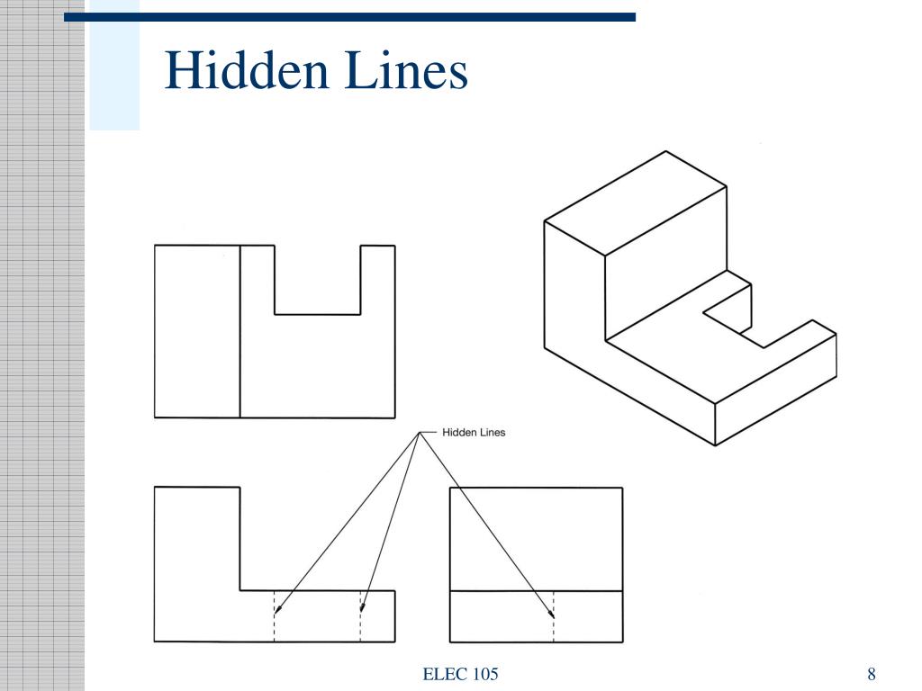
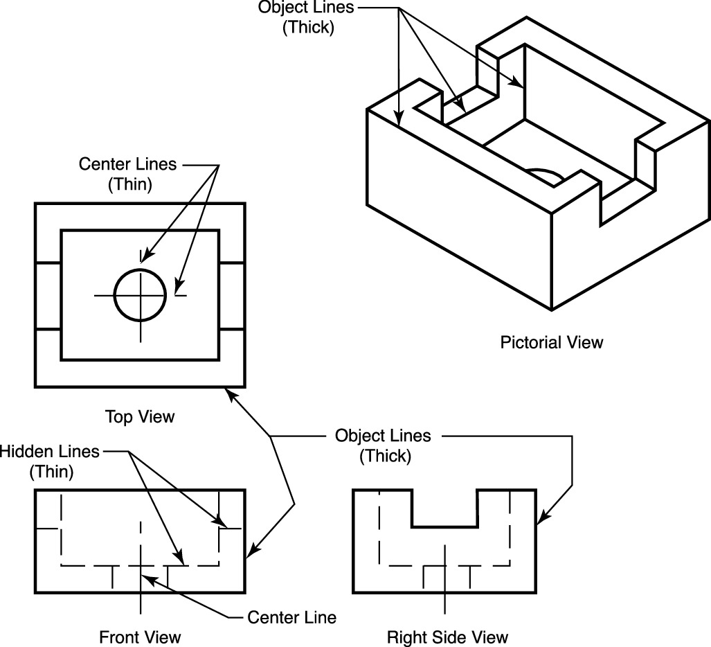
A variety of line styles graphically represent physical objects. These features are typically inside the object or obscured by other surfaces. Web hidden lines in a drawing represent the edges where surfaces meet but are not directly visible. Web standard engineering drawing line types. Curved lines (arcs, circles, and ellipses) cutting plane lines. The dashed line is used to indicate hidden details like hidden outlines and hidden edges. As the name suggest, they are visible in an engineering drawing. There are also lines used in some particular cases: 28k views 9 years ago. (1) visible lines, (2) hidden lines, (3) center lines.
28k views 9 years ago. The dashed line may be either thick or thin, but only one type (thick or thin) should be used on a single drawing or set of drawings. These lines are drawn to represent hidden or invisible edges of the objects. Hidden lines will always begin and end with a dash. These features are typically inside the object or obscured by other surfaces. Hidden lines are 0.3 mm thin dashed line. Web hidden lines in a drawing represent the edges where surfaces meet but are not directly visible. Centerlines are one of the most frequently used tools in engineering drawing. These features are typically inside the object or obscured by other surfaces. Their basic purpose is to show circular/cylindrical features in a drawing, which are found in abundance in mechanical parts.

Hidden Lines and Center Lines YouTube
These types of lines also known as object lines. Randy64 (aerospace) (op) 15 jan 15 16:00. When drawn under these guidelines, the lines parallel to these three axes are at their true (scale) lengths. These features are typically inside the object or obscured by other surfaces. Hidden lines are represented by a series of short dashes, evenly spaced, with the.
2020 Drawing Hidden Lines for an Orthographic drawing using alignment
My checker and i were looking for it this morning. Hidden lines are represented by a series of short dashes, evenly spaced, with the first. There are also lines used in some particular cases: Web standard engineering drawing line types. Hidden lines are omitted from pictorial drawings unless they are needed to make the drawing clear.

Type of Line used in (ED) Engineering Drawing Phantom line hidden
Centerlines are one of the most frequently used tools in engineering drawing. Web hidden edge lines are drawn with short dashes and are used to show hidden features of an. Web hidden detail & lines in engineering drawing & cad. Web there are 12 types of lines usually used in engineering drawing. I have heard two schools of thought concerning.
Types Of Lines In Engineering Drawing
They represent dashed lines, which are useful for. Hidden lines are omitted from pictorial drawings unless they are needed to make the drawing clear. In the example above, a visible edge and hidden edge both project to the same line, so a. These types of lines also known as object lines. Web hidden lines are used in engineering drawings to.

Hidden Lines Drafting drafting engineering
When an object becomes more complex, as in the case of an automobile engine block, a clearer presentation of the interior can be made by sketching the object as it would look if it were cut apart. My checker and i were looking for it this morning. (1) visible lines, (2) hidden lines, (3) center lines. Hidden lines are represented.
PPT Engineering Drawing PowerPoint Presentation, free download ID
Hidden lines are omitted from pictorial drawings unless they are needed to make the drawing clear. A variety of line styles graphically represent physical objects. Centerlines are one of the most frequently used tools in engineering drawing. The dashed line is used to indicate hidden details like hidden outlines and hidden edges. Hidden lines will always begin and end with.

ENGR 1304 Ch2 Views and Perspectives
(1) visible lines, (2) hidden lines, (3) center lines. Hidden lines show edges and contours of important features that are obscured by the geometry of the part. Web hidden detail & lines in engineering drawing & cad. Web there are 12 types of lines usually used in engineering drawing. Web in an isometric drawing, the object’s vertical lines are drawn.

Engineering Drawing Hidden Lines for Info TECHNOLOGY and INFORMATION
A hidden line should begin with a dash in contact with the line from which it starts, except when it is the continuation of an unbroken line. Web hidden detail & lines in engineering drawing & cad. (1) visible lines, (2) hidden lines, (3) center lines. An engineering drawing is a subcategory of technical drawings. Recognizing such dashed lines while.

Different Types of LINES in Engineering Drawing//Classification of
My checker and i were looking for it this morning. The purpose is to convey all the information necessary for manufacturing a product or a part. Web there are 12 types of lines usually used in engineering drawing. Visible lines are dark and thick. As the name suggest, they are visible in an engineering drawing.
Quick Reference For Using Technical Drawings Scroll Saw Woodworking
Sometimes they are used to make a drawing easier to understand. They are dark and thick lines of any engineering design drawing. Their basic purpose is to show circular/cylindrical features in a drawing, which are found in abundance in mechanical parts. There are also lines used in some particular cases: Common examples of such features include bolt holes, pins, discs,.
Web 18.06.2020 By Andreas Velling.
Dimensions should be shown in true profile views and refer to visible outlines. Web standard engineering drawing line types. Figure 3.46 shows a case in which hidden lines are needed because a projecting part cannot be clearly shown without them. When drawn under these guidelines, the lines parallel to these three axes are at their true (scale) lengths.
I Have Heard Two Schools Of Thought Concerning Hidden Lines:
Hidden lines are represented by a series of short dashes, evenly spaced, with the first. They are drawn as short dashes that are equally spaced. Web hidden lines in a drawing represent the edges where surfaces meet but are not directly visible. (1) visible lines, (2) hidden lines, (3) center lines.
Hidden Lines Are 0.3 Mm Thin Dashed Line.
The dashed line may be either thick or thin, but only one type (thick or thin) should be used on a single drawing or set of drawings. Common examples of such features include bolt holes, pins, discs, etc. Web hidden edge lines are drawn with short dashes and are used to show hidden features of an. Section lines, or hatching, that represent the cut surface usually consist of thin parallel lines, as shown below, drawn at an angle of approximately 45° to the principal edges or axes of the part.
The Dashed Line Is Used To Indicate Hidden Details Like Hidden Outlines And Hidden Edges.
Web when multiple edges project to the same line on the drawing, the line type is determined by the following precedence: In the example above, a visible edge and hidden edge both project to the same line, so a. Their basic purpose is to show circular/cylindrical features in a drawing, which are found in abundance in mechanical parts. They are 0.6 mm thick.