How To Draw A Bode Diagram
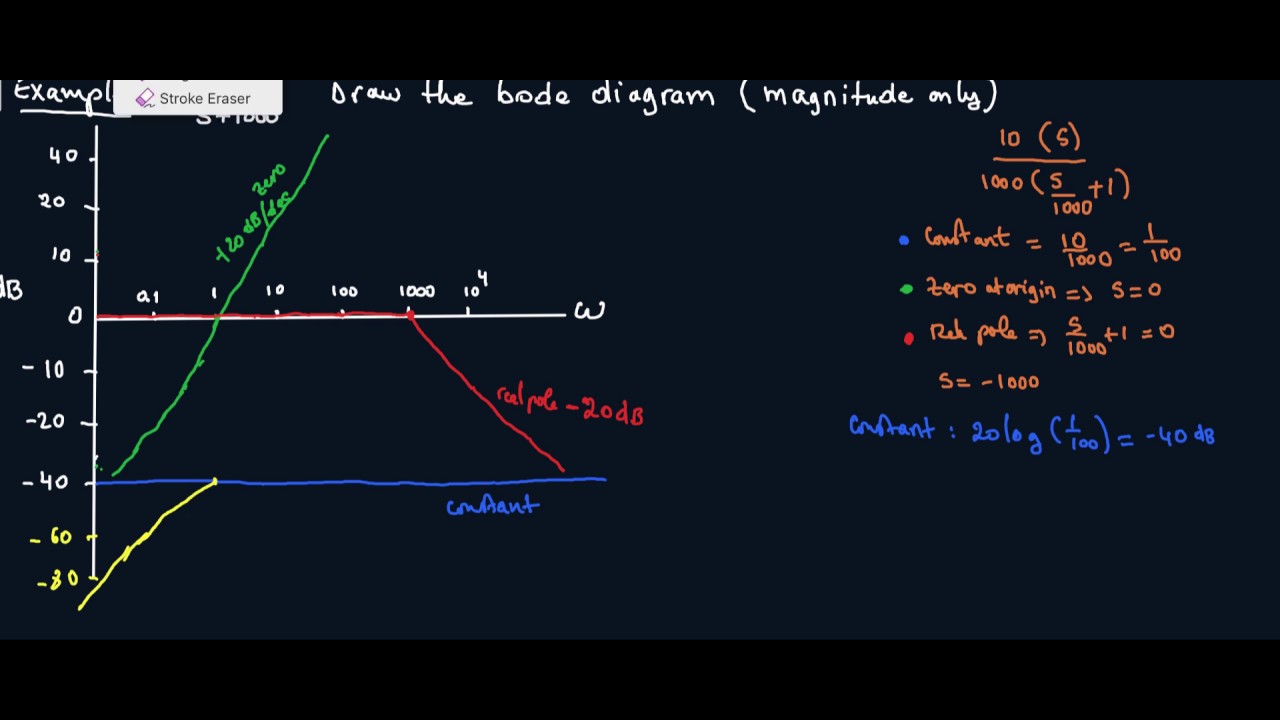
How To Draw A Bode Diagram - You can choose between these three. Web the first step to produce a bode plot sketch is to factor the numerator and denominator in terms of its poles and zeros: The gain is plotted in decibels, while frequency is shown on a. Web learn how to draw a bode diagram by understanding the effect of different terms in the transfer function. Draw the bode diagram for the transfer function: Web the bode magnitude plot is a graph of the absolute value of the gain of a circuit, as a function of frequency. Web how to generate a bode plot in pspice. Choose the independent variable used in the transfer function. Make both the lowest order term in the numerator. The table below summarizes what to do for each type of term in a bode plot.
Now let us discuss the procedure of drawing a bode plot:. −40 −20 0 20 40 magnitude (db) 103 104 105 106 107 ω (rad/s). Make both the lowest order term in the numerator. An important characteristic of an analog circuitry is the behavior of the transfer function as. The table below summarizes what to do for each type of term in a bode plot. • draw your vertical and horizontal axis. Web keeping all the above points in mind, we are able to draw a bode plot for any kind of control system. See examples of how to sketch the log magnitude and phase plots for. G ( s) = s + 2 ( s + 1) ( s + 10). Draw the bode diagram for the transfer function:
Choose the independent variable used in the transfer function. Rewrite the transfer function in proper form. Web the first step to produce a bode plot sketch is to factor the numerator and denominator in terms of its poles and zeros: For the development of dynamic systems in electrical engineering, control. Bode(sys) bode(sys1,sys2,.,sysn) bode(sys1,linespec1,.,sysn,linespecn) bode( ___ ,w) [mag,phase,wout] = bode(sys) [mag,phase,wout] = bode(sys,w). Web enter the transfer function. An important characteristic of an analog circuitry is the behavior of the transfer function as. Choose the type of bode plot you want to draw. Now let us discuss the procedure of drawing a bode plot:. Web how to generate a bode plot in pspice.

Bode Plot EXAMPLE YouTube
G ( s) = s + 2 ( s + 1) ( s + 10). Web how to generate a bode plot with ltspice. Draw the bode diagram for the transfer function: Make both the lowest order term in the numerator. Web enter the transfer function.
How to Draw a Bode Plot (Part 2) YouTube
Make both the lowest order term in the numerator. Web 8 rows rules for drawing bode diagrams. −40 −20 0 20 40 magnitude (db) 103 104 105 106 107 ω (rad/s). The bode plot or the bode diagram consists of two plots −. Bode plot introduction bode plots give engineers a way to visualize the effect of their circuit, in.

ME 340 Example Drawing Bode Plot of a Transfer Function 2 YouTube
An important characteristic of an analog circuitry is the behavior of the transfer function as. Make both the lowest order term in the numerator. Web 8 rows rules for drawing bode diagrams. Choose the independent variable used in the transfer function. −40 −20 0 20 40 magnitude (db) 103 104 105 106 107 ω (rad/s).

simple method to draw bode plot3 YouTube
An important characteristic of an analog circuitry is the behavior of the transfer function as. Choose the independent variable used in the transfer function. The bode plot or the bode diagram consists of two plots −. • draw your vertical and horizontal axis. Web how to generate a bode plot with ltspice.

51. Bode Plot 3 Bode plot of a complex conjugate pair of pole YouTube
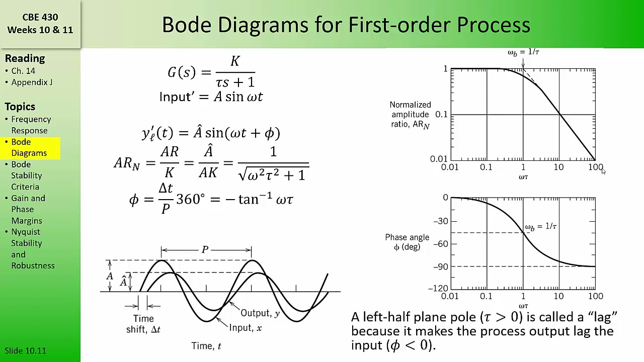
Web we draw its intersection with the frequency axis where ω = ωc, since that’s where the magnitude is 0 db. The gain is plotted in decibels, while frequency is shown on a. An important characteristic of an analog circuitry is the behavior of the transfer function as. Bode plot introduction bode plots give engineers a way to visualize the.

Sketching Bode diagrams a rapid introduction YouTube
Web learn how to draw a bode diagram by understanding the effect of different terms in the transfer function. G ( s) = s + 2 ( s + 1) ( s + 10). The bode plot or the bode diagram consists of two plots −. Draw the bode diagram for the transfer function: A bode plot consists of.

Bode Plot Example Bode Diagram Example MATLAB Electrical Academia
Bode plot introduction bode plots give engineers a way to visualize the effect of their circuit, in terms of voltage magnitude and phase angle (shift). For the development of dynamic systems in electrical engineering, control. Web we draw its intersection with the frequency axis where ω = ωc, since that’s where the magnitude is 0 db. G ( s) =.

how to draw bode plot in MATLAB Bode plot using MATLAB MATLAB
G ( s) = s + 2 ( s + 1) ( s + 10). Bode plot introduction bode plots give engineers a way to visualize the effect of their circuit, in terms of voltage magnitude and phase angle (shift). Designtech over 2 years ago. A bode plot consists of. Web learn how to draw a bode diagram by understanding.

Bode Plot Example Bode Diagram Example MATLAB Electrical Academia
Web keeping all the above points in mind, we are able to draw a bode plot for any kind of control system. Bode plot introduction bode plots give engineers a way to visualize the effect of their circuit, in terms of voltage magnitude and phase angle (shift). Bode(sys) bode(sys1,sys2,.,sysn) bode(sys1,linespec1,.,sysn,linespecn) bode( ___ ,w) [mag,phase,wout] = bode(sys) [mag,phase,wout] = bode(sys,w). A.
CBE 430 Week 10 04 Bode diagrams part 1 YouTube
• draw your vertical and horizontal axis. The table below summarizes what to do for each type of term in a bode plot. Web learn how to draw a bode diagram by understanding the effect of different terms in the transfer function. Bode(sys) bode(sys1,sys2,.,sysn) bode(sys1,linespec1,.,sysn,linespecn) bode( ___ ,w) [mag,phase,wout] = bode(sys) [mag,phase,wout] = bode(sys,w). This is also available as a.
For The Development Of Dynamic Systems In Electrical Engineering, Control.
See examples of how to sketch the log magnitude and phase plots for. Web we draw its intersection with the frequency axis where ω = ωc, since that’s where the magnitude is 0 db. G ( s) = s + 2 ( s + 1) ( s + 10). Web how to generate a bode plot in pspice.
An Important Characteristic Of An Analog Circuitry Is The Behavior Of The Transfer Function As.
Choose the independent variable used in the transfer function. The gain is plotted in decibels, while frequency is shown on a. • draw your vertical and horizontal axis. Now let us discuss the procedure of drawing a bode plot:.
This Is Also Available As A Word Document Or Pdf.
Designtech over 2 years ago. Web how to generate a bode plot with ltspice. Web the bode magnitude plot is a graph of the absolute value of the gain of a circuit, as a function of frequency. Web the first step to produce a bode plot sketch is to factor the numerator and denominator in terms of its poles and zeros:
Web Learn How To Draw A Bode Diagram By Understanding The Effect Of Different Terms In The Transfer Function.
Rewrite the transfer function in proper form. Web keeping all the above points in mind, we are able to draw a bode plot for any kind of control system. You can choose between these three. Bode plot introduction bode plots give engineers a way to visualize the effect of their circuit, in terms of voltage magnitude and phase angle (shift).