How To Draw Shear Diagram
How To Draw Shear Diagram - To calculate the bending moment of a beam, we must work in the same way we did for the. Finally calculating the moments can be done in the following steps: I explain the calculus involved in drawing them and the steps are written out below.check out. Continuing on the next force is 21.67 lb upward at the a support. Web learn to draw shear force and moment diagrams using 2 methods, step by step. There is a long way and a quick way to do them. Keep moving across the beam, stopping at every load that acts on the beam. This is a beam with distributed. Also, draw shear and moment. Web to analyze the internal shearing forces and moments in these beams we could use shear and moment diagrams.
Web axial, shear, and bending moment diagrams (afd, sfd, and bmd) show the internal forces and moments along a structural member. Draw out a free body diagram of the body horizontally. By drawing the free body diagram you identify all of these loads and show then on a sketch. To create the shear force diagram, we will use the following process. Solve for all external forces acting on the body. To create the shear force diagram, we will use the following process. Draw a vertical line of same length as the value of applied force at the point. When you get to a load, add to the shear force diagram by the amount of the force. They help determine the material, size, and type of a member given a set of loads it can support without structural failure. They allow us to see where the maximum loads occur so that we can optimize the design to prevent failures and reduce the overall weight and cost of the structure.
This is a beam with distributed. Web 5.3 drawing the shear force diagram. Web egr2312 lab experiment n°8 shearing and bending moment diagrams 1. A shear force diagram is a valuable tool used in structural engineering to represent the distribution of shear force along a beam or any other structural element. As force acting at point a in our case is 20 kn downward, so. To create the shear force diagram, we will use the following process. To create the shear force diagram, we will use the following process. Draw out a free body diagram of the body horizontally. Start drawing shear force diagram from any of the extreme ends. To create the shear force diagram, we will use the following process.

Draw The Shear Diagram For The Beam Photos Cantik
Web to analyze the internal shearing forces and moments in these beams we could use shear and moment diagrams. Assume that the beam is cut at point c a distance of x from he left support and the portion of the beam to the right of c be removed. To create the shear force diagram, we will use the following.

How To Draw Shear Diagrams Approvaldeath13
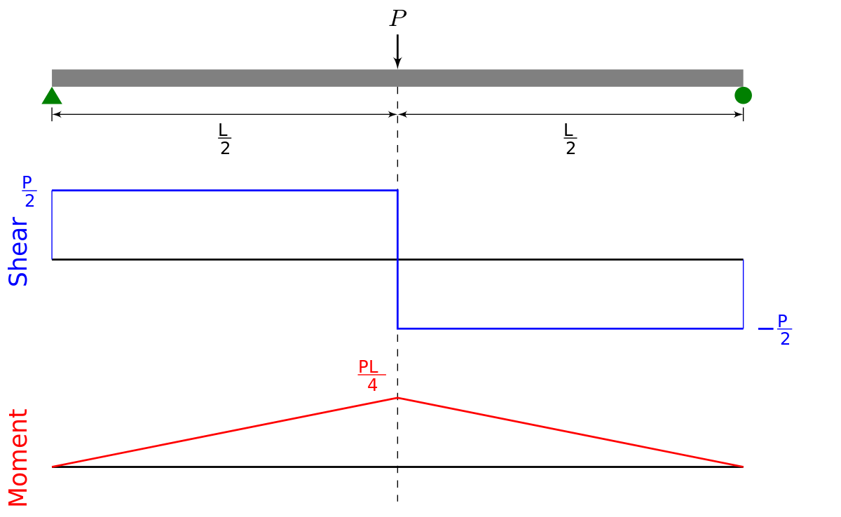
There is a long way and a quick way to do them. Draw out a free body diagram of the body horizontally. Web shear and moment diagrams are graphs which show the internal shear and bending moment plotted along the length of the beam. Web being able to draw shear force diagrams (sfd) and bending moment diagrams (bmd) is a.
Drawing Shear and Moment Diagrams Example Mechanics of Materials and
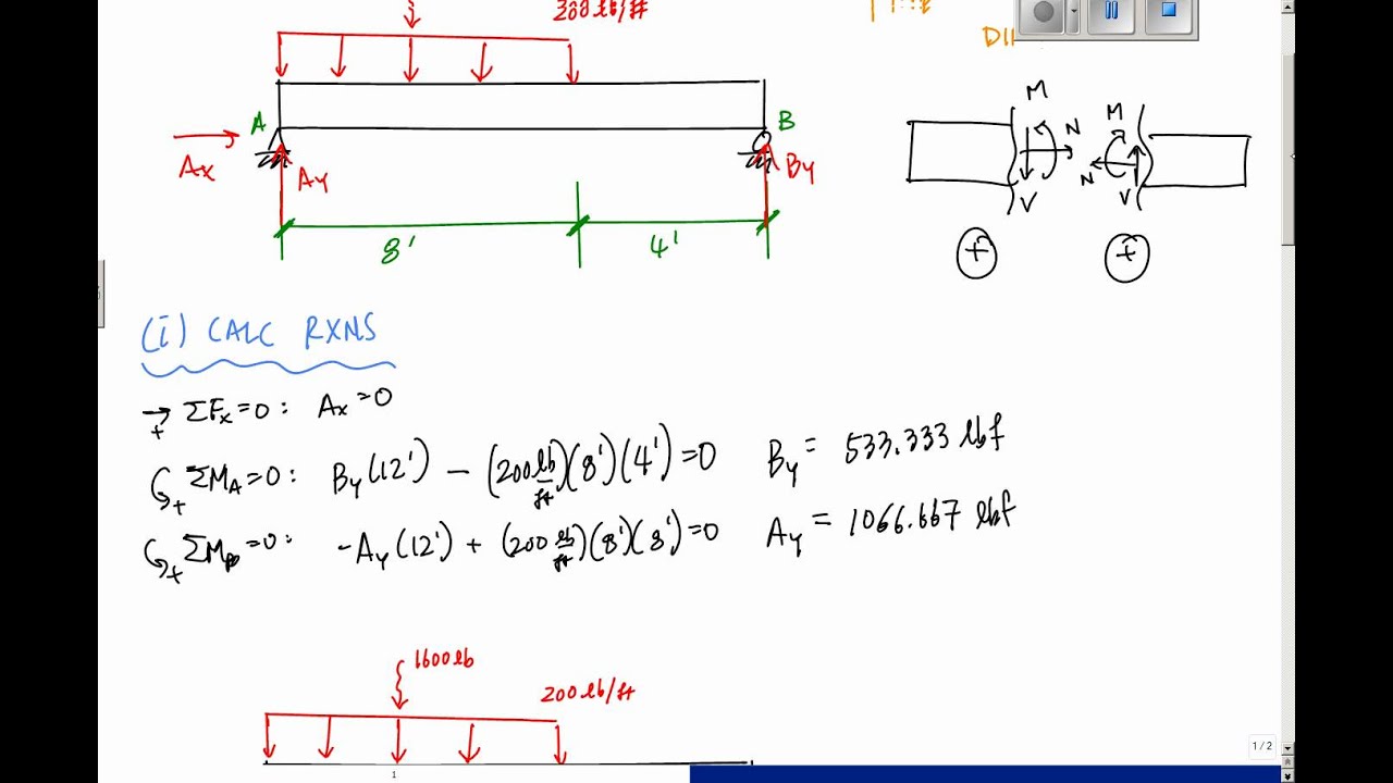
By drawing the free body diagram you identify all of these loads and show then on a sketch. Web this is an example problem that will show you how to graphically draw a shear and moment diagram for a beam. Web in this video i explain how to draw shear and moment diagrams. Knowing forces effect on beams. Suppose we.

Learn How To Draw Shear Force And Bending Moment Diagrams Engineering
Draw a vertical line of same length as the value of applied force at the point. Web egr2312 lab experiment n°8 shearing and bending moment diagrams 1. Solve for all external forces acting on the body. Continuing on the next force is 21.67 lb upward at the a support. Web 𝐌𝐲 𝐄𝐧𝐠𝐢𝐧𝐞𝐞𝐫𝐢𝐧𝐠 𝐍𝐨𝐭𝐞𝐛𝐨𝐨𝐤 for notes!

How to Draw a Shear and Moment Diagram A Comprehensive Guide
It is a graphical representation with the position of the beam plotted along the. Web 𝐌𝐲 𝐄𝐧𝐠𝐢𝐧𝐞𝐞𝐫𝐢𝐧𝐠 𝐍𝐨𝐭𝐞𝐛𝐨𝐨𝐤 for notes! Web this is an example problem that will show you how to graphically draw a shear and moment diagram for a beam. Draw out a free body diagram of the body horizontally. Since beams primarily support vertical loads the axial.
How To Draw A Shear Force Diagram Corestep vrogue.co
We go through breaking a beam into segments, and then we learn about the relatio. Web this video is an introduction to shear force and bending moment diagrams.what are shear forces and bending moments?shear forces and bending moments are resul. Keep moving across the beam, stopping at every load that acts on the beam. I explain the calculus involved in.
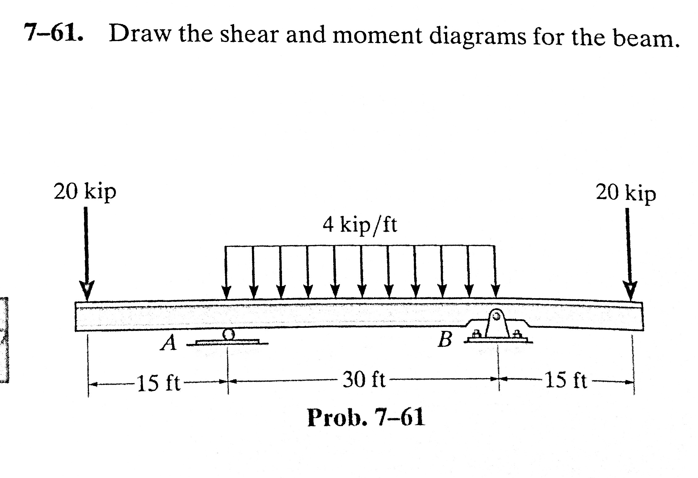
Solved 761. Draw the shear and moment diagrams for the
Solve for all external forces acting on the body. Web this video is an introduction to shear force and bending moment diagrams.what are shear forces and bending moments?shear forces and bending moments are resul. This is a beam with distributed. A shear force diagram is a valuable tool used in structural engineering to represent the distribution of shear force along.

How to draw shear and moment diagrams YouTube
There is a long way and a quick way to do them. Finally calculating the moments can be done in the following steps: Our approach to drawing the shear force diagram is actually very straightforward. Web 5.3 drawing the shear force diagram. In this case we have come to a negative 20kn force, so we will minus 20kn from the.

Easier way to quickly draw shear diagrams YouTube
To correctly determine the shear forces and bending moments along a beam we need to know all of the loads acting on it, which includes external loads and reaction loads at supports. Web in this video i explain how to draw shear and moment diagrams. Draw out a free body diagram of the body horizontally. When you get to a.

Learn How To Draw Shear Force And Bending Moment Diagrams Engineering
Solve for all external forces acting on the body. If force acting on the point is downward then the vertical line should go downward or else upward. Knowing forces effect on beams. I explain the calculus involved in drawing them and the steps are written out below.check out. To create the shear force diagram, we will use the following process.
They Help Determine The Material, Size, And Type Of A Member Given A Set Of Loads It Can Support Without Structural Failure.
Web shear diagrams always begin and end at zero, with all of the forces on the member shown in between.starting from the left, the first force you come across is the 10 lb downward force at the left end. Draw out a free body diagram of the body horizontally. To create the shear force diagram, we will use the following process. This is a beam with distributed.
In This Experiment, We Will Work On Drawing The Shear And Bending Diagram Of A Beam.
Web in this video i explain how to draw shear and moment diagrams. From left to right, make “cuts” before and after each reaction/load. Web once you have the reactions, draw your free body diagram and shear force diagram underneath the beam. Web being able to draw shear force diagrams (sfd) and bending moment diagrams (bmd) is a critical skill for any student studying statics, mechanics of materials, or structural engineering.
Lined Up Below The Free Body Diagram, Draw A Set.
Leave all distributed forces as distributed forces and do not replace them with the equivalent point load. Continuing on the next force is 21.67 lb upward at the a support. Assume that the beam is cut at point c a distance of x from he left support and the portion of the beam to the right of c be removed. This is the first point of data, draw a line from zero to negative 10.
Web Learn To Draw Shear Force And Moment Diagrams Using 2 Methods, Step By Step.
Web axial, shear, and bending moment diagrams (afd, sfd, and bmd) show the internal forces and moments along a structural member. We go through breaking a beam into segments, and then we learn about the relatio. They allow us to see where the maximum loads occur so that we can optimize the design to prevent failures and reduce the overall weight and cost of the structure. Web egr2312 lab experiment n°8 shearing and bending moment diagrams 1.