Iso Pipe Drawing
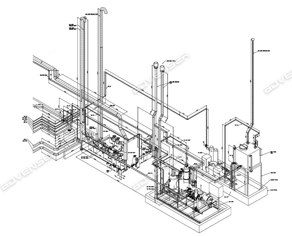
Iso Pipe Drawing - In the world of industrial projects, precision and accuracy are of utmost importance. 66k views 1 year ago tutorials for pipe fitters and. Web isometric drawings are typically used to show the details of a piping system, such as the size and type of piping, the direction of flow of the fluids, and the location of valves, pumps, and other equipment nozzles. How to read iso drawings. Pipe size is always written at any connecting point of isometric. Isometric drawings are commonly used in industries such as the oil and gas industry, petrochemical industry, and plumbing for planning, design, construction, and pipeline maintenance. No more tedious material tracking when creating a pipe isometric drawing. Piping joint types, weld types. Web pipeline isometric drawings are crucial visual representations in the fields of engineering and construction. These drawings provide a detailed 3d illustration of a piping system, offering a comprehensive view of.
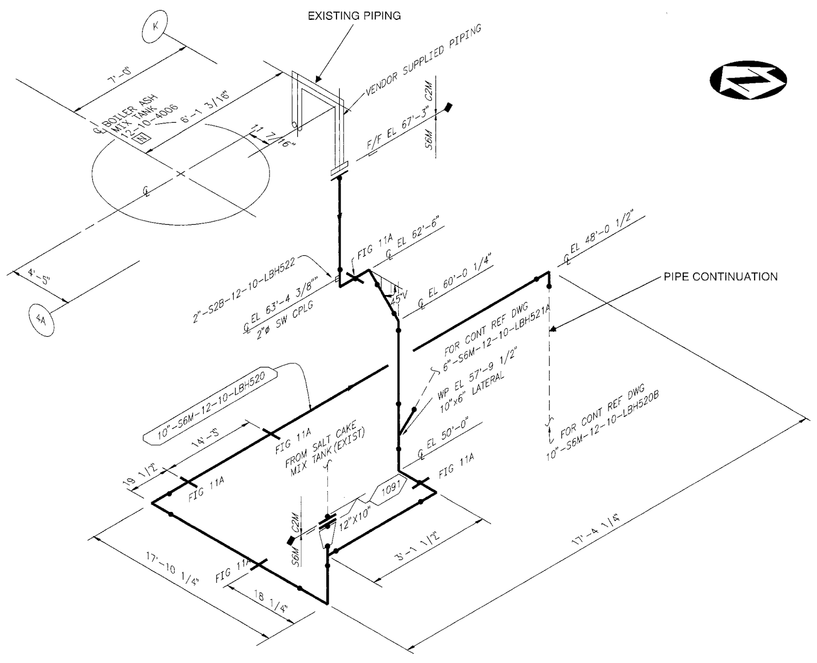
Web an isometric drawing is a type of pictorial drawing in which three sides of an object can be seen in one view. We are concluding our first pipefitter series run with a video on how to draw isometric drawings. Iso pipes are typically drawn using specialized software such as avicad which supports isometric drawings. Web the iso, as isometric are commonly referred, is oriented on the grid relative to the north arrow found on plan drawings. Pipe size is always written at any connecting point of isometric. Web a piping isometric drawing provides all the required information like: Subscribe to autodesk virtual academy. 66k views 1 year ago tutorials for pipe fitters and. Web how to read piping isometric drawings. Piping fabrication work is based on isometric drawings.
Because iso's are not drawn to scale, dimensions are required to specify exact lengths of piping runs. Web a piping isometric drawing provides all the required information like: Tutorial piping tips and tricks. Dimensions and location of instruments. Piping iso symbols and meaning. Piping fabrication work is based on isometric drawings. Web the iso, as isometric are commonly referred, is oriented on the grid relative to the north arrow found on plan drawings. Isometric drawings are commonly used in industries such as the oil and gas industry, petrochemical industry, and plumbing for planning, design, construction, and pipeline maintenance. It is the most important deliverable of piping engineering department. Piping isometric drawing is a representation of 3d view of piping layout of the plant.
Isometric Piping Drawings Advenser
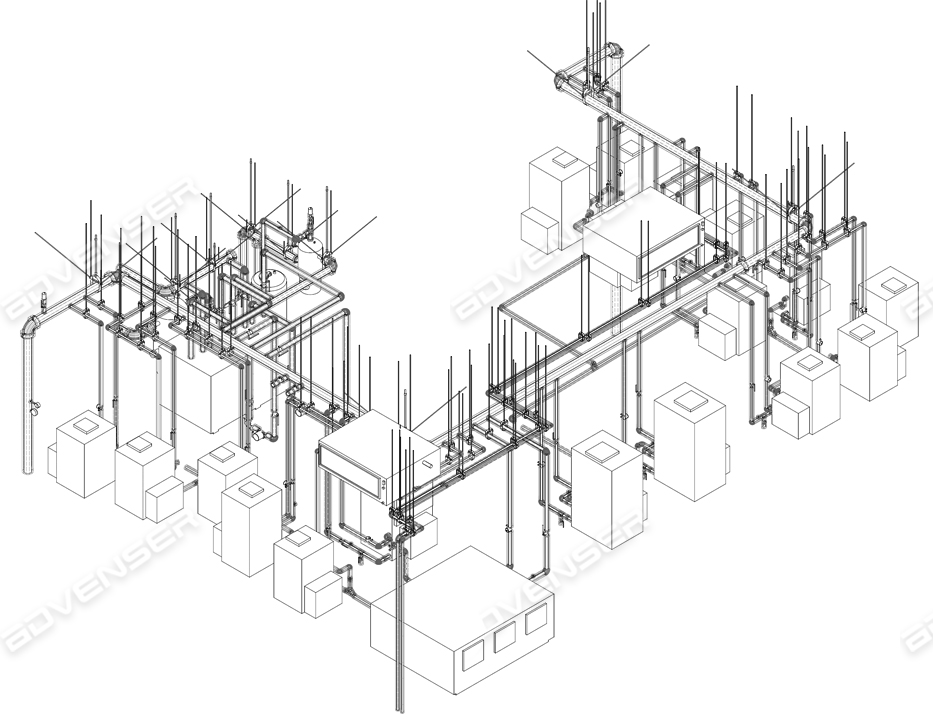
Pipe size is always written at any connecting point of isometric. Web pipeline isometrics are detailed drawings used in engineering and design to represent the 3d layout of a pipeline system on a 2d surface. Web m4 iso is the ideal tool for automatically generating unscaled piping isometric drawings from your 3d pipework models. Pipe lengths are determined through calculations.
Sample Iso Piping Drawing
Use m4 iso fx with your current 3d piping design system to generate piping isometrics from your pcf files. 9k views 2 years ago autodesk inventor | ketiv virtual academy. Piping fabrication work is based on isometric drawings. Web creating a piping isometric drawing. It is the most important deliverable of piping engineering department.
Isometric Pipe Drawing at GetDrawings Free download
Web how to read piping isometric drawings. Piping isometric drawing consists of three sections. Web piping isometric drawing is an isometric representation of single pipe line in a plant. No more tedious material tracking when creating a pipe isometric drawing. Tutorial piping tips and tricks.

How to read piping Isometric drawing YouTube
It’s popular within the process piping industry because it can be laid out and drawn with ease and portrays the. Lighter lines show connected pipe, and are not parts of the symbols. It is the most important deliverable of piping engineering department. Piping and component descriptions with size, quantity, and material codes. These drawings provide a detailed 3d illustration of.

How to read piping isometric drawing, Pipe fitter training, Watch the
Subscribe to autodesk virtual academy. Pipe size is always written at any connecting point of isometric. Web pipeline isometric drawings are crucial visual representations in the fields of engineering and construction. Web how to read piping isometric drawings. Web the iso, as isometric are commonly referred, is oriented on the grid relative to the north arrow found on plan drawings.

How to read piping isometric drawing pdf fleetlio
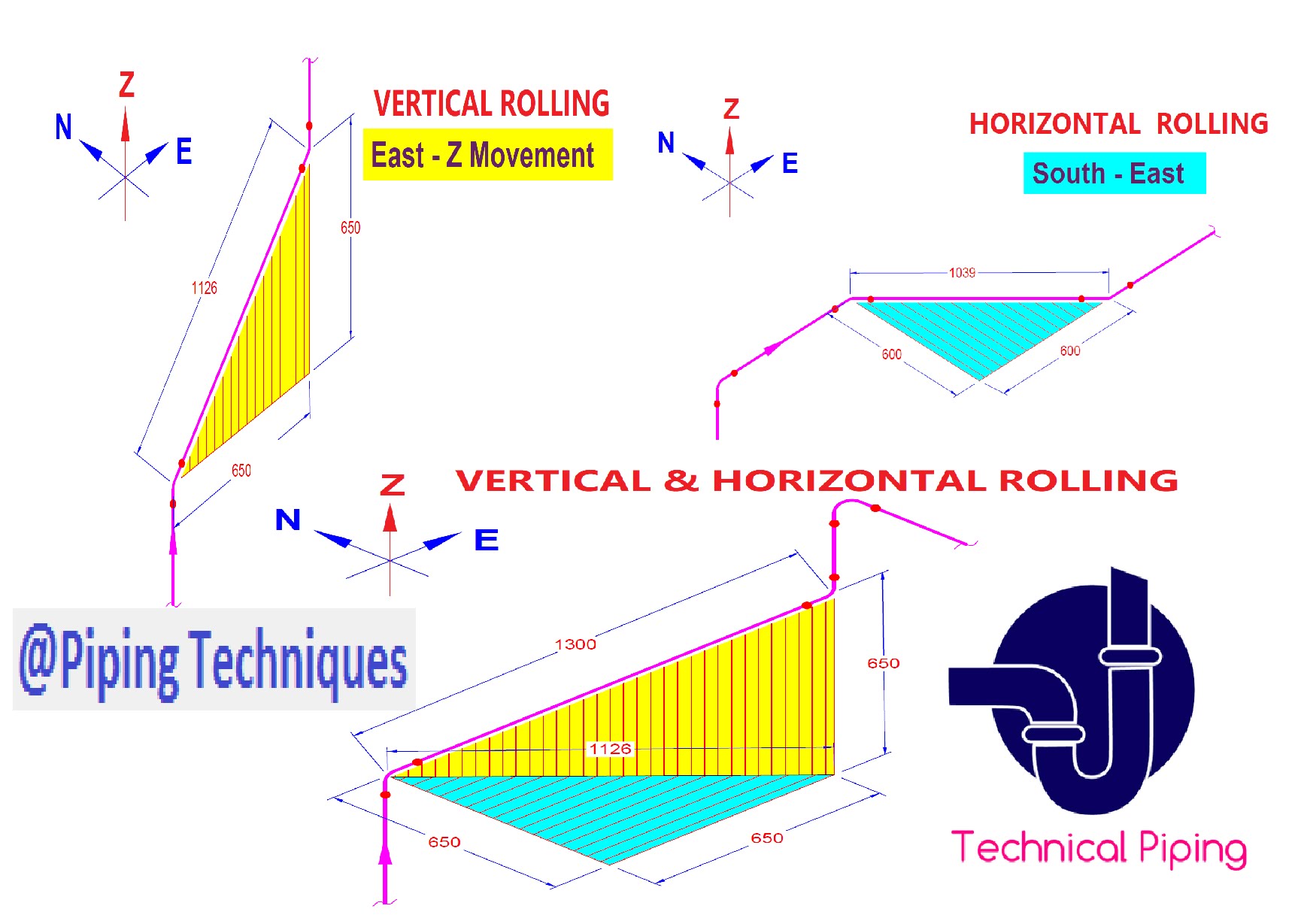
Although the pipeline is accurately dimensioned, it is deliberately not drawn to scale and therefore does not correspond exactly to a real. Web isometric drawings are typically used to show the details of a piping system, such as the size and type of piping, the direction of flow of the fluids, and the location of valves, pumps, and other equipment.
Revit AddOns EzISO Piping Models to Isometric Drawings
Web piping isometric drawing is an isometric representation of single pipe line in a plant. Pipe lengths are determined through calculations using coordinates and elevations. Subscribe to autodesk virtual academy. What is covered in this course. Because iso's are not drawn to scale, dimensions are required to specify exact lengths of piping runs.
Reading isometric pipe drawings panrewa
Web drawing piping isometrics : Pipe lengths are determined through calculations using coordinates and elevations. Web © 2024 google llc. Web create isometric drawings in minutes: Piping isometric drawing dimensions are always from center to center of pipe.

How to read isometric drawing piping dadver
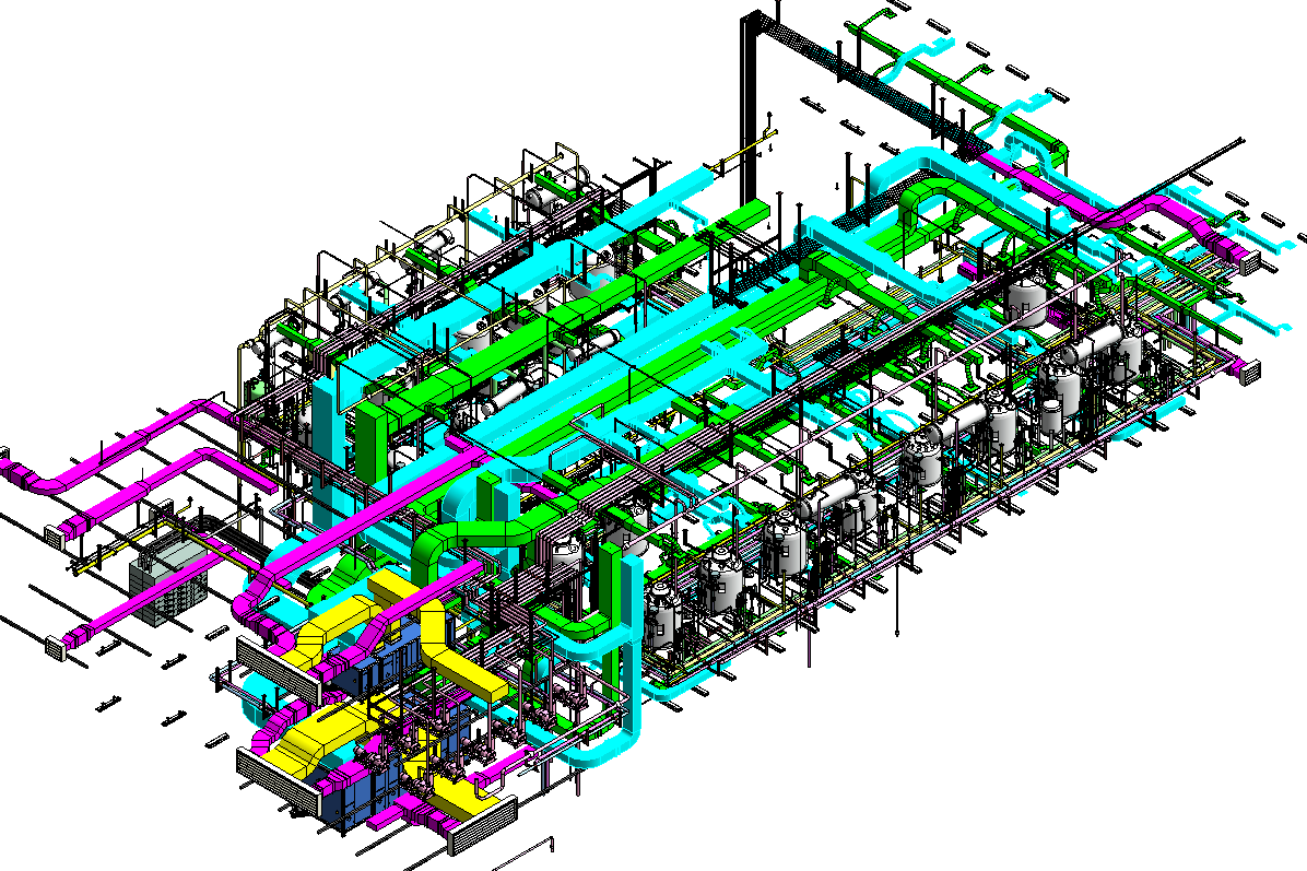
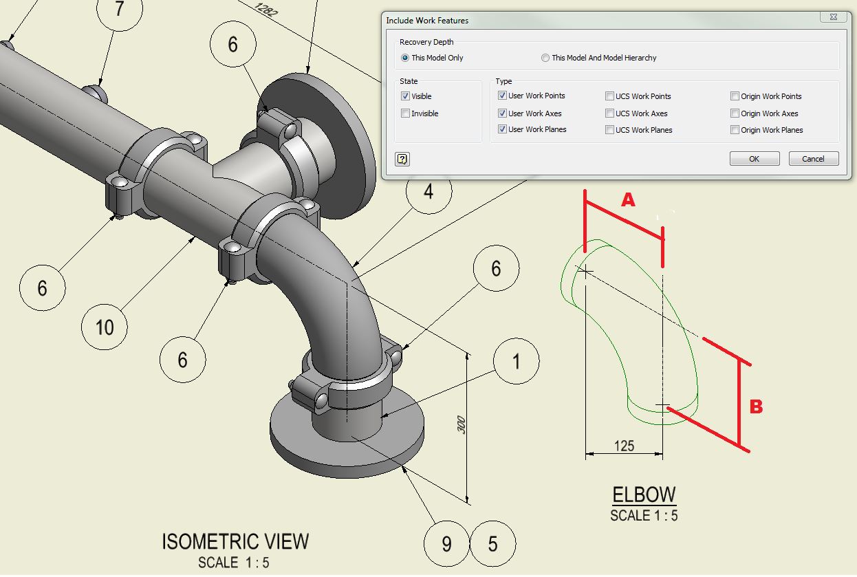
Tutorial piping tips and tricks. Unlike orthographic drawings that show different views (front, side, and top) separately, isometric drawings combine these views into a. Piping isometric drawing is a representation of 3d view of piping layout of the plant. Web isometric drawings are typically used to show the details of a piping system, such as the size and type of.
Piping Isometric Drawings Autodesk Community
Web piping isometric drawing is an isometric representation of single pipe line in a plant. Although the pipeline is accurately dimensioned, it is deliberately not drawn to scale and therefore does not correspond exactly to a real. They serve as precise illustrations providing essential information about the layout, dimensions, materials, and key components of a pipeline system. 3 clicks to.
Import Idf Or Pcf Files.
No more tedious material tracking when creating a pipe isometric drawing. Piping isometric drawing consists of three sections. They serve as precise illustrations providing essential information about the layout, dimensions, materials, and key components of a pipeline system. Web a piping isometric drawing is a technical illustration that presents a 3d representation of a piping system.
It’s Popular Within The Process Piping Industry Because It Can Be Laid Out And Drawn With Ease And Portrays The.
Use m4 iso fx with your current 3d piping design system to generate piping isometrics from your pcf files. Web the iso, as isometric are commonly referred, is oriented on the grid relative to the north arrow found on plan drawings. Web a piping isometric drawing is a technical drawing that depicts a pipe spool or a complete pipeline using an isometric representation. We are concluding our first pipefitter series run with a video on how to draw isometric drawings.
Unlike Orthographic Drawings That Show Different Views (Front, Side, And Top) Separately, Isometric Drawings Combine These Views Into A.
Piping joint types, weld types. Web picad® is a piping design software that lets you create clear piping isometrics quickly and affordably. Web pipeline isometric drawings are crucial visual representations in the fields of engineering and construction. Iso pipes are typically drawn using specialized software such as avicad which supports isometric drawings.
Web Symbols Are Shown In Black Lines.
Web how to read piping isometrics using real plant drawings. It is the most important deliverable of piping engineering department. Web piping isometric drawing is an isometric representation of single pipe line in a plant. What you will get in this course.