Isometric Piping Drawing
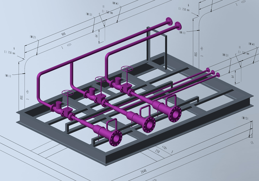
Isometric Piping Drawing - 1) show all major equipment, its north/south and east/west orientation, and all piping leading to and from equipment are developed by piping designers. Piping isometric drawings are detailed technical illustrations that show a 3d view of piping systems. Web the minimum inputs for isometric sketching are: Piping isometric drawing consists of three sections. In very complex or large piping systems, piping isometrics are essential to the design and manufacturing phases of a project. Work from hand sketches or just draw them directly. Web what are pipeline isometric drawings? Piping joint types, weld types. Web isometric drawings are typically used to show the details of a piping system, such as the size and type of piping, the direction of flow of the fluids, and the location of valves, pumps, and other equipment nozzles. Web picad® is a piping design software that lets you create clear piping isometrics quickly and affordably.
Trusted by companies like bilfinger, bp and shell, picad® saves you time and ensures accurate construction. Web an isometric drawing is a type of pictorial drawing in which three sides of an object can be seen in one view. Web creating a piping isometric drawing. It is the most important deliverable of piping engineering department. Piping isometric drawings are detailed technical illustrations that show a 3d view of piping systems. Web master piping isometrics with our comprehensive guide: Among various applications, isometric drawing finds extensive use in the field of engineering, particularly in the design and construction of pipes. They serve as precise illustrations providing essential information about the layout, dimensions, materials, and key components of a pipeline system. Standards and conventions for valve status; Mechanical data sheets (mds) in some of the cases, more detailed piping layout will be available.
Work from hand sketches or just draw them directly. Iso pipes are typically drawn using specialized software such as avicad which supports isometric drawings. 9k views 2 years ago autodesk inventor | ketiv virtual academy. Among various applications, isometric drawing finds extensive use in the field of engineering, particularly in the design and construction of pipes. Unlike orthographic drawings that show different views (front, side, and top) separately, isometric drawings combine these views into a. We are concluding our first pipefitter series run with a video on how to draw isometric drawings. What is covered in this course. Piping isometric drawing is a representation of 3d view of piping layout of the plant. Piping isometric drawing dimensions are always from center to center of pipe. Piping joint types, weld types.
Isometric Pipe Drawing at GetDrawings Free download
Piping isometric drawings are detailed technical illustrations that show a 3d view of piping systems. Web learn how to draw your own piping isometrics through numerous real industrial examples. Web a piping isometric drawing is a technical illustration that presents a 3d representation of a piping system. Work from hand sketches or just draw them directly. Web easy isometric is.

How to read piping Isometric drawing YouTube
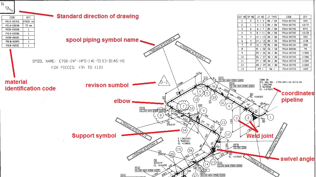
Web to read piping isometric drawing you must know the following things: This is because it enables a pipe work manufacturer to determine exactly how the pipeline will run and. Mechanical data sheets (mds) in some of the cases, more detailed piping layout will be available. Process & instrumentation diagram (p & id) 3. It is an axonometric projection in.

Piping Design Basics Piping Isometric Drawings Piping Isometrics
Piping isometric drawing dimensions are always from center to center of pipe. Piping isometric drawing consists of three sections. Standards and conventions for valve status; Web a piping isometric drawing is a technical illustration that presents a 3d representation of a piping system. Unlike orthographic drawings that show different views (front, side, and top) separately, isometric drawings combine these views.

Piping Isometric Drawing at Explore collection of
In very complex or large piping systems, piping isometrics are essential to the design and manufacturing phases of a project. No more tedious material tracking when creating a pipe isometric drawing. The piping isometric drawing is used both for documentation and for the production of the pipelines. Quickly produce installation isometrics and fabrication spool drawings. Web a piping isometric drawing.
Automatic Piping Isometrics from 3D Piping Designs M4 ISO
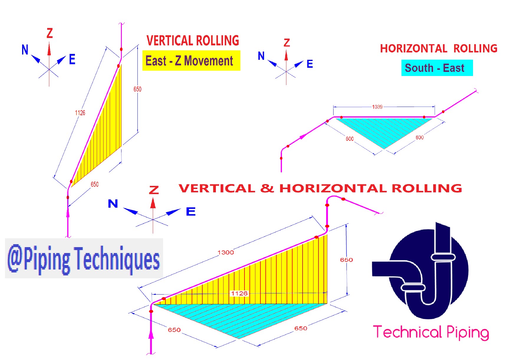
Web basic piping isometric symbols : This is because it enables a pipe work manufacturer to determine exactly how the pipeline will run and. It is an axonometric projection in which the three coordinate axes appear equally foreshortened and the angle between any two of them is 120 degrees. Web what are pipeline isometric drawings? Piping iso symbols and meaning.

How to read piping isometric drawing, Pipe fitter training, Watch the
Discover the essentials of piping isometrics, including how they simplify complex piping systems for construction, maintenance, and documentation purposes. Web a piping isometric drawing provides all the required information like: Web a piping isometric drawing is a simple representation of the pipeline, which nevertheless contains all relevant information and dimensions. Piping isometric drawings are detailed technical illustrations that show a.
Instrumentation Today HOW TO READ AN ISOMETRIC PIPING DRAWING
Web piping isometrics are generally produced from orthographic drawings and are important pieces of information to engineers. Subscribe to autodesk virtual academy. It’s popular within the process piping industry because it can be laid out and drawn with ease and portrays the. Web piping isometric drawing is an isometric representation of single pipe line in a plant. Standards and conventions.
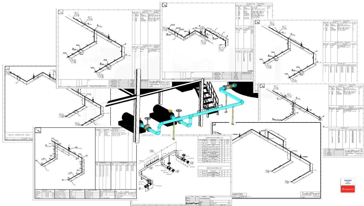
How to create piping isometric drawings with SOLIDWORKS
Among various applications, isometric drawing finds extensive use in the field of engineering, particularly in the design and construction of pipes. Web learn how to draw your own piping isometrics through numerous real industrial examples. It’s popular within the process piping industry because it can be laid out and drawn with ease and portrays the. Piping isometric drawing is a.

Isometric Piping Drawings Advenser
Web basic piping isometric symbols : Web a piping isometric drawing is a simple representation of the pipeline, which nevertheless contains all relevant information and dimensions. Web what are pipeline isometric drawings? This is because it enables a pipe work manufacturer to determine exactly how the pipeline will run and. 1) show all major equipment, its north/south and east/west orientation,.
Learn isometric drawings (piping isometric)
Piping isometric drawing is a representation of 3d view of piping layout of the plant. As you draw, the bom generates and updates itself automatically. It’s popular within the process piping industry because it can be laid out and drawn with ease and portrays the. Trusted by companies like bilfinger, bp and shell, picad® saves you time and ensures accurate.
Piping Isometric Drawing Dimensions Are Always From Center To Center Of Pipe.
Web what are pipeline isometric drawings? 9k views 2 years ago autodesk inventor | ketiv virtual academy. The piping isometric drawing is used both for documentation and for the production of the pipelines. In very complex or large piping systems, piping isometrics are essential to the design and manufacturing phases of a project.
Piping And Component Descriptions With Size, Quantity, And Material Codes.
These highly structured drawings provide a comprehensive 3d representation of the arrangement, dimensions, and connections of pipes within a system. Mechanical data sheets (mds) in some of the cases, more detailed piping layout will be available. Web isometric drawings are typically used to show the details of a piping system, such as the size and type of piping, the direction of flow of the fluids, and the location of valves, pumps, and other equipment nozzles. Piping plan drawings/general arrangement drawings (gad) the piping plan or general arrangement drawings (fig.
Web Learn How To Draw Your Own Piping Isometrics Through Numerous Real Industrial Examples.
Web a piping isometric drawing is a simple representation of the pipeline, which nevertheless contains all relevant information and dimensions. Web piping isometrics are generally produced from orthographic drawings and are important pieces of information to engineers. Web to read piping isometric drawing you must know the following things: How to read iso drawings.
Iso Pipes Are Typically Drawn Using Specialized Software Such As Avicad Which Supports Isometric Drawings.
Piping iso symbols and meaning. Unlike orthographic drawings that show different views (front, side, and top) separately, isometric drawings combine these views into a. Reading tips, symbols, and drawing techniques for engineers and piping professionals. Web a piping isometric drawing is a technical illustration that presents a 3d representation of a piping system.