Isometric Projection In Engineering Drawing
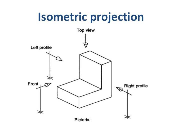
Isometric Projection In Engineering Drawing - Draw a pictorial or an isometric projection from orthographic projections of simple solids or objects bounded by plane surfaces. Web the four basic steps for creating an isometric drawing are: Only one view on a plane is drawn. Construct isometric planes, using the overall width (w), isometric views for solids height (h), and depth (d) of the object, such that the. These lines are called isometric axes. Do not dimension the drawing. When drawn under these guidelines, the lines parallel to these three axes are at their true (scale) lengths. The technique is intended to combine the illusion of depth, as in a perspective rendering, with the undistorted presentation of the object’s principal dimensions. In an isometric drawing, the object’s vertical lines are drawn vertically, and the horizontal lines in the width and depth planes are shown at 30 degrees to the horizontal. It is an axonometric projection in which the three coordinate axes appear equally foreshortened and the angle between any two of them is 120 degrees.
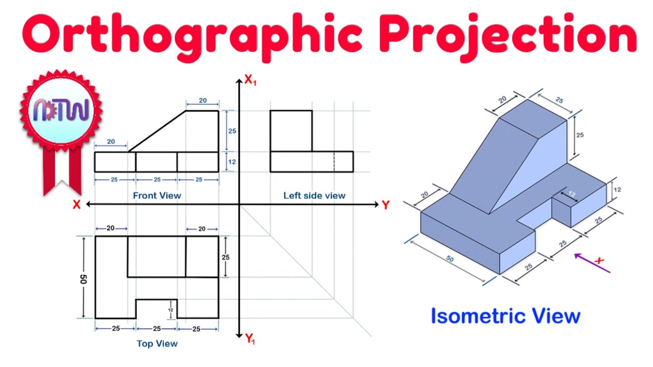
Web in an isometric drawing, the object’s vertical lines are drawn vertically, and the horizontal lines in the width and depth planes are shown at 30 degrees to the horizontal. Construct isometric planes, using the overall width (w), isometric views for solids height (h), and depth (d) of the object, such that the. Web in this video, i have explained how to draw an orthographic view of an object from an isometric view. These lines are called isometric axes. Isometric drawings are easy once you learn the basic techniques. Web in this video we will learn the basics of #axonometricprojection and #isometricprojection and solve #objectiveproblems for #eseprelims. It is an axonometric projection in which the three coordinate axes appear equally foreshortened and the angle between any two of them is 120 degrees. Whether you're a seasoned engineer or just starting your journey, this. This type maintains uniform foreshortening along all three axes. The width and depth dimensions of an isometric projection are drawn at 30° above the horizontal.
In an isometric projection, the plane is placed in such a way that all the, three visible sides of the object make same angle with one another. Web in this video, i have explained how to draw an orthographic view of an object from an isometric view. The width and depth dimensions of an isometric projection are drawn at 30° above the horizontal. Isometric axes, lines and planes: Draw a pictorial or an isometric projection from orthographic projections of simple solids or objects bounded by plane surfaces. In an isometric drawing, the object’s vertical lines are drawn vertically, and the horizontal lines in the width and depth planes are shown at 30 degrees to the horizontal. It is an axonometric projection in which the three coordinate axes appear equally foreshortened and the angle between any two of them is 120 degrees. Web chapter 4, isometric projections, 4.1 introduction, isometric projection is a type of pictorial projection in which all the three dimensions of the, solid are shown in one view. Construct isometric planes, using the overall width (w), isometric views for solids height (h), and depth (d) of the object, such that the. These lines are called isometric axes.

Isometric view and Orthographic Projection Engineering Drawing Top
I'll cover all the basics of isometric drawing for engineering and technical d. Do not dimension the drawing. Web learn to draw isometric projections using these simple steps provided. The width and depth dimensions of an isometric projection are drawn at 30° above the horizontal. In an isometric projection, the plane is placed in such a way that all the,.

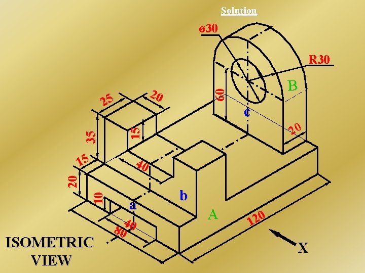
Engineering Drawing Isometric Projections EXAMPLE 1 YouTube
Web in this comprehensive tutorial, we delve into the art of creating flawless isometric views using orthographic projections. Web the four basic steps for creating an isometric drawing are: Make a the lowest point of the drawing. These lines are called isometric axes. Web purpose of isometric drawing is to understand overall shape, size & appearance of an object prior.

Engineering Drawing Isometric Projections Example 2 YouTube
Web in an isometric drawing, the object’s vertical lines are drawn vertically, and the horizontal lines in the width and depth planes are shown at 30 degrees to the horizontal. Also their actual sizes can be measured directly from the view., fig. Web in this video, i'll teach you all you need to know about isometric projection. Construct isometric planes,.
![A Beginner's Guide to Isometric Projection [With Examples]](https://www.theengineerspost.com/wp-content/uploads/2019/10/Isometric-Projection-of-a-Cube-A-1.jpg)
A Beginner's Guide to Isometric Projection [With Examples]
Construct isometric planes, using the overall width (w), isometric views for solids height (h), and depth (d) of the object, such that the. These drawings are particularly useful for conveying a clear understanding of how different parts of a structure fit together. Mutually perpendicular plane surfaces of an object and the edges formed by these surfaces are equally inclined to.
Orthographic Projection from isometric view in Engineering drawing
Draw a pictorial or an isometric projection from orthographic projections of simple solids or objects bounded by plane surfaces. Web in this video, i'll teach you all you need to know about isometric projection. Web axonometric projection is a parallel projection technique used to create a pictorial drawing of an object by rotating the object on an axis relative to.

Engineering Drawing Isometric Projections Example 3 YouTube
Web to facilitate the easy and quick method of measurement of lengths of the various edges in their reduced sizes while drawing the isometric projection of the object, a special scale known as the isometric scale is constructed. I'll cover all the basics of isometric drawing for engineering and technical d. Web the four basic steps for creating an isometric.
What is an Isometric Drawing? Types And Step To Draw
Web to facilitate the easy and quick method of measurement of lengths of the various edges in their reduced sizes while drawing the isometric projection of the object, a special scale known as the isometric scale is constructed. Also their actual sizes can be measured directly from the view., fig. Web the four basic steps for creating an isometric drawing.

ISOMETRIC TO ORTHOGRAPHIC PROJECTION SUM NO 1 TECHNICAL DRAWING
Web in this comprehensive tutorial, we delve into the art of creating flawless isometric views using orthographic projections. Web to facilitate the easy and quick method of measurement of lengths of the various edges in their reduced sizes while drawing the isometric projection of the object, a special scale known as the isometric scale is constructed. These lines are called.
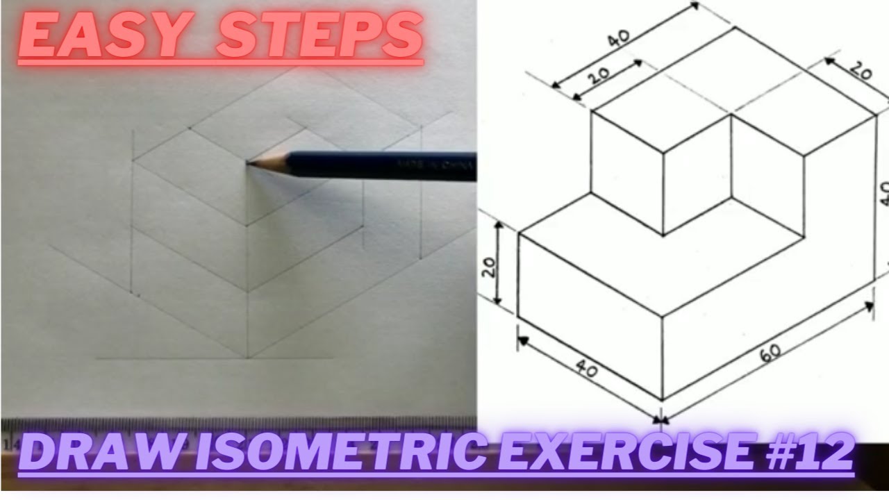
How to draw ISOMETRIC PROJECTIONS Technical Drawing Exercise 12
Do not dimension the drawing. Isometric drawings are easy once you learn the basic techniques. The width and depth dimensions of an isometric projection are drawn at 30° above the horizontal. I'll cover all the basics of isometric drawing for engineering and technical d. In an isometric projection, the plane is placed in such a way that all the, three.
Isometric Drawing, Projection Its Types, Methods.
Also their actual sizes can be measured directly from the view., fig. Web in this video, i have explained how to draw an orthographic view of an object from an isometric view. In an isometric projection, the plane is placed in such a way that all the, three visible sides of the object make same angle with one another. This.
Web To Facilitate The Easy And Quick Method Of Measurement Of Lengths Of The Various Edges In Their Reduced Sizes While Drawing The Isometric Projection Of The Object, A Special Scale Known As The Isometric Scale Is Constructed.
The width and depth dimensions of an isometric projection are drawn at 30° above the horizontal. Web in this video, i have explained how to draw an orthographic view of an object from an isometric view. Web in this video, i'll teach you all you need to know about isometric projection. It is an axonometric projection in which the three coordinate axes appear equally foreshortened and the angle between any two of them is 120 degrees.
The Technique Is Intended To Combine The Illusion Of Depth, As In A Perspective Rendering, With The Undistorted Presentation Of The Object’s Principal Dimensions.
When drawn under these guidelines, the lines parallel to these three axes are at their true (scale) lengths. 4.1 shows a cube standing on a corner g (o) with all the faces of the cube are equally, , inclined. In an isometric drawing, the object’s vertical lines are drawn vertically, and the horizontal lines in the width and depth planes are shown at 30 degrees to the horizontal. In this way, all the three sides meet at a point making an angle of 120° with one another.
Isometric Axes, Lines And Planes:
Web in this video we will learn the basics of #axonometricprojection and #isometricprojection and solve #objectiveproblems for #eseprelims. These lines are called isometric axes. Web in an isometric drawing, the object’s vertical lines are drawn vertically, and the horizontal lines in the width and depth planes are shown at 30 degrees to the horizontal. Make a the lowest point of the drawing.
Web Learn To Draw Isometric Projections Using These Simple Steps Provided.
A dimension listed on an engineering drawing is known as the _______ _______. Whether you're a seasoned engineer or just starting your journey, this. Do not dimension the drawing. It is an axonometric projection in which the three coordinate axes appear equally foreshortened and the angle between any two of them is 120 degrees.