One Line Drawings Electrical
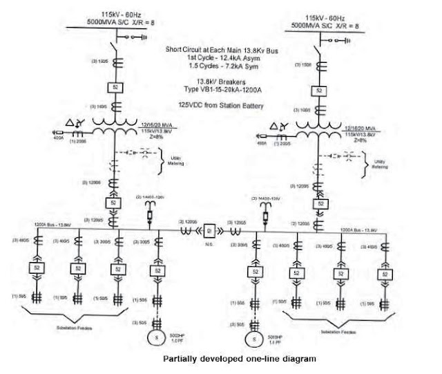
One Line Drawings Electrical - Wiring diagrams show specific electrical connections. Web by the end of this video will completely understand the ideals of the one line diagram from a electrical perspective. Web initially, the single line diagram (sld) provides a framework for the incorporation of different types of required information such as: Web this electrical one line diagram is the primary reference for maintenance and operations for lockout/tagout procedures, as well as for any engineering power system studies. It is a simplified drawing of the whole system or a portion of the power system that shows the electrical placement of all major equipment. Depicts electrical devices as drawings or pictures connected by lines representing wires. It is the first step in preparing a critical response plan, allowing you to become thoroughly familiar with the electrical distribution system layout and design in your facility. Shows how components are related to others on the same circuit, but contains less detailed information about electrical connections. Web single line diagrams are used in common engineering practice as graphical representation of electrical switchboard or assembly containing more sections, i.e. A single line can show all or part of a system.
It is a graphical representation of a circuit or. We will looking a normal set of plans o. It will have one single line shown for bus (or cable) to represent all three phases. 14k views 3 years ago electrical videos. Image used courtesy of schneider electric. Depicts electrical devices as drawings or pictures connected by lines representing wires. A single line can show all or part of a system. Web we usually depict the electrical distribution system by a graphic representation called a single line diagram (sld). Web we usually depict the electrical distribution system by a graphic representation called a single line diagram (sld). It is used by electricians, engineers, and technicians to understand the electrical components and connections within a system.
Shows how components are related to others on the same circuit, but contains less detailed information about electrical connections. Web single line diagram. Web this electrical one line diagram is the primary reference for maintenance and operations for lockout/tagout procedures, as well as for any engineering power system studies. Web we usually depict the electrical distribution system by a graphic representation called a single line diagram (sld). Web by r jagan mohan rao. It is a graphical representation of a circuit or. Depicts electrical devices as drawings or pictures connected by lines representing wires. Web by the end of this video will completely understand the ideals of the one line diagram from a electrical perspective. Web in electrical engineering, a single line diagram is a simplified representation of an electrical power system or electrical grid that shows the flow of electricity through the system. A block diagram is a type of electrical drawings that represents the principle components of a complex system in the form of blocks interconnected by lines that represent their relation.
how to prepare electrical single line diagram Wiring Diagram and
Web initially, the single line diagram (sld) provides a framework for the incorporation of different types of required information such as: Web we usually depict the electrical distribution system by a graphic representation called a single line diagram (sld). A block diagram is a type of electrical drawings that represents the principle components of a complex system in the form.
Electrical Single Line Diagram Part Two Electrical Knowhow
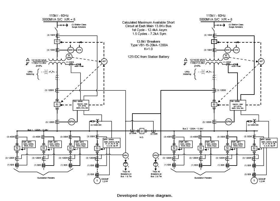
Web this electrical one line diagram is the primary reference for maintenance and operations for lockout/tagout procedures, as well as for any engineering power system studies. It is a simplified drawing of the whole system or a portion of the power system that shows the electrical placement of all major equipment. 14k views 3 years ago electrical videos. It will.
Electrical Single Line Diagram Template (DWG) — LINE DRAW CAD LAB
Incoming service voltage and utilization voltages required. It is used by electricians, engineers, and technicians to understand the electrical components and connections within a system. A single line can show all or part of a system. Ladder diagram or line diagram. It will have one single line shown for bus (or cable) to represent all three phases.

Simplified Electrical Oneline Diagram for the Forrestal Building
Ladder diagram or line diagram. Web an electrical single line diagram is a graphical representation of an electrical system’s components and connections. It is the first step in preparing a critical response plan, allowing you to become thoroughly familiar with the electrical distribution system layout and design in your facility. A single line can show all or part of a.
How To Calculate and Draw a Single Line Diagram For The Power System EEP
A single line can show all or part of a system. We will looking a normal set of plans o. Depicts electrical devices as drawings or pictures connected by lines representing wires. Web in electrical engineering, a single line diagram is a simplified representation of an electrical power system or electrical grid that shows the flow of electricity through the.

How to Read and Understand an Electrical Single Line Diagram?
Web by r jagan mohan rao. It is used by electricians, engineers, and technicians to understand the electrical components and connections within a system. Web initially, the single line diagram (sld) provides a framework for the incorporation of different types of required information such as: Wiring diagrams show specific electrical connections. Shows how components are related to others on the.
Electrical Single Line Diagram Part Two Electrical Knowhow
Web we usually depict the electrical distribution system by a graphic representation called a single line diagram (sld). Web single line diagram. It is used by electricians, engineers, and technicians to understand the electrical components and connections within a system. 14k views 3 years ago electrical videos. In this post, i will show why you need an sld and how.

Single Line Diagram of Power Plant Power Systems
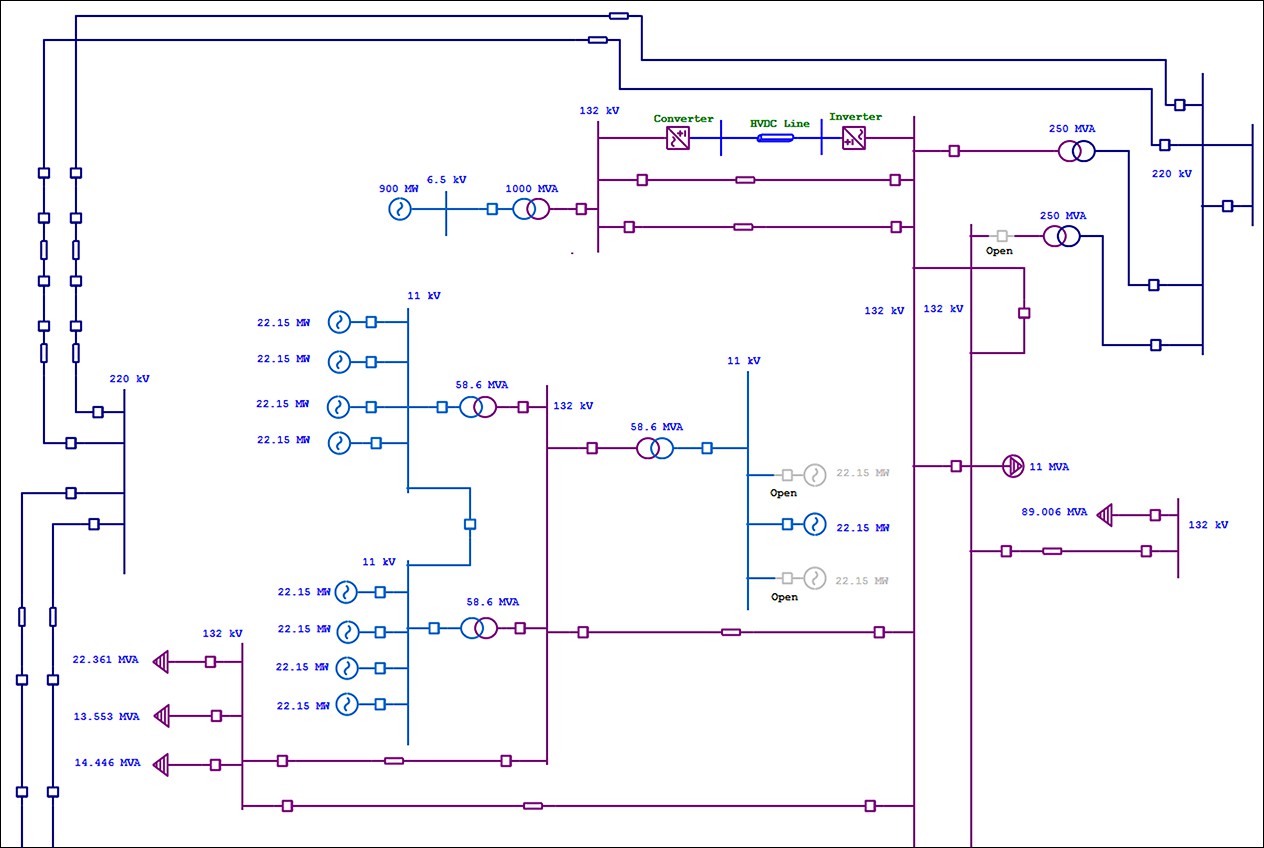
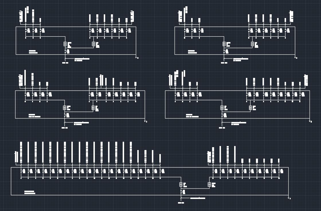
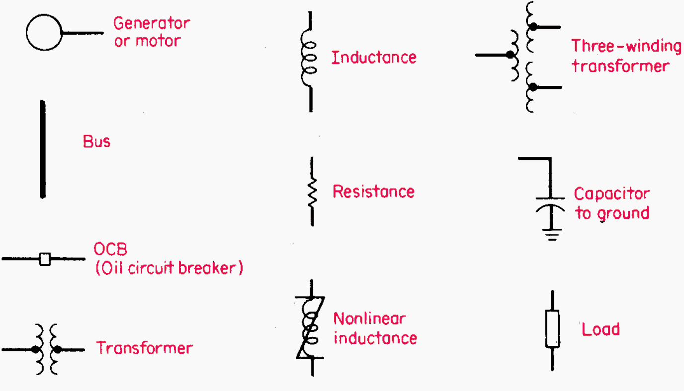
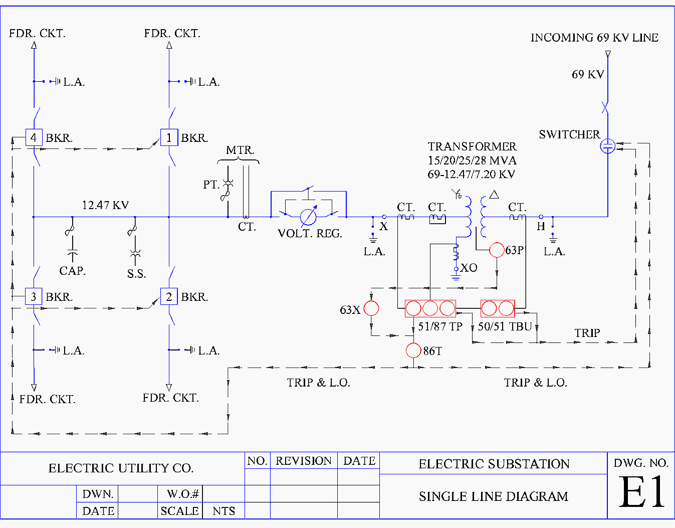
A single line can show all or part of a system. It uses standardized symbols to depict various elements such as generators, transformers, switches, motors, and protective devices. We will looking a normal set of plans o. Main components such as transformers, switches, and breakers are indicated by their standard graphic symbol. Web single line diagrams are used in common.
Understanding Substation Single Line Diagrams and IEC 61850 Process Bus
Symbols and lines are used to represent the nodes and connections in the system, and electrical characteristics may be included as well. We will looking a normal set of plans o. Web we usually depict the electrical distribution system by a graphic representation called a single line diagram (sld). Incoming service voltage and utilization voltages required. Image used courtesy of.
Intelligent One Line Diagram Electrical SingleLine Diagram ETAP
Ladder diagram or line diagram. Web in electrical engineering, a single line diagram is a simplified representation of an electrical power system or electrical grid that shows the flow of electricity through the system. Web single line diagrams are used in common engineering practice as graphical representation of electrical switchboard or assembly containing more sections, i.e. It will have one.
Image Used Courtesy Of Schneider Electric.
It is the first step in preparing a critical response plan, allowing you to become thoroughly familiar with the electrical distribution system layout and design in your facility. Wiring diagrams show specific electrical connections. Incoming service voltage and utilization voltages required. Web single line diagrams are used in common engineering practice as graphical representation of electrical switchboard or assembly containing more sections, i.e.
Web By R Jagan Mohan Rao.
Web single line diagram. A single line can show all or part of a system. Web there are three basic types of wiring diagrams: It will have one single line shown for bus (or cable) to represent all three phases.
Web One Line May Even Represent Multiple Conductors With Other Devices Between Them.
It uses standardized symbols to depict various elements such as generators, transformers, switches, motors, and protective devices. Web by the end of this video will completely understand the ideals of the one line diagram from a electrical perspective. A single line can show all or part of a system. It is used by electricians, engineers, and technicians to understand the electrical components and connections within a system.
Depicts Electrical Devices As Drawings Or Pictures Connected By Lines Representing Wires.
Web this electrical one line diagram is the primary reference for maintenance and operations for lockout/tagout procedures, as well as for any engineering power system studies. In this post, i will show why you need an sld and how to make it. Web in electrical engineering, a single line diagram is a simplified representation of an electrical power system or electrical grid that shows the flow of electricity through the system. Web we usually depict the electrical distribution system by a graphic representation called a single line diagram (sld).