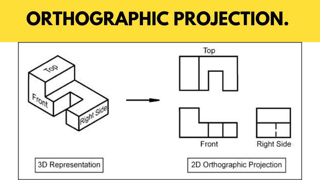
Orthographic Engineering Drawing
Orthographic Engineering Drawing - Web orthographic projection (also orthogonal projection and analemma). When multiple edges project to the same line on the drawing, the line type is determined by the following precedence: (1) visible lines, (2) hidden lines, (3) center. On an orthographic or isometric drawing. Thus, a 2d view has to convey everything necessary for part production. Now, since we’re drawing on paper we can’t quite make it 3d, so we call it an isometric drawing. This kind of representation allows avoiding any kind of distortion of lengths. Orthographic projection is a form of parallel projection in which the top, front, and side. Draw the following lines with 100 mm len gth. From mastering orthographic projection to honing your skills in dimensioning, embark on a journey where lines, curves, and dimensions converge to bring ideas to life.
In this comprehensive tutorial, we delve into the art of creating flawless isometric views using orthographic projecti. In isometric projection, the most commonly used form of axonometric projection in engineering drawing, the direction of viewing is such that the three axes of space appear equally foreshortened, and there is a common angle of 120° between them. If the isometric drawing can show all details and all dimensions on one drawing, it is ideal. A complete understanding of the object should be possible from the drawing. Orthographic drawings are also known as multiviews. Web understand what orthographic drawing is by learning its definition and reviewing orthographic drawing examples. This kind of representation allows avoiding any kind of distortion of lengths. (1) visible lines, (2) hidden lines, (3) center. Web also called orthographic projection, orthographic drawings present different perspective points of a 2d image of an object to allow for a clearer visualization than isometric drawing, which is a 3d rendering that only uses one point of perspective. Web welcome back, engineering enthusiasts!
Draw the following lines with 100 mm len gth. Web orthographic projection (also orthogonal projection and analemma). An auxiliary view is an orthographic view that is projected into any plane other than one of the six primary views. These views are typically used when an object contains some sort of inclined plane. This spatial visualization skill is different from our last activity, during which we worked on representing objects. The most commonly used views are top. Web any engineering drawing should show everything: Orthographics are also called engineering drawings or plan views. Web orthographic projections are a way of describing what an object looks like from several different views. Web in other words, equal distances do not appear equal on a perspective drawing.
Engineering Drawing Views & Basics Explained Fractory
Geometrical figures are in two dimensions, hence they may be drawn to their actual sizes and shapes on a sheet of paper as it is also in two dimensions. In isometric projection, the most commonly used form of axonometric projection in engineering drawing, the direction of viewing is such that the three axes of space appear equally foreshortened, and there.

ORTHOGRAPHIC PROJECTION IN ENGINEERING DRAWING YouTube
This spatial visualization skill is different from our last activity, during which we worked on representing objects. On an orthographic or isometric drawing. Geometrical figures are in two dimensions, hence they may be drawn to their actual sizes and shapes on a sheet of paper as it is also in two dimensions. Web any engineering drawing should show everything: This.

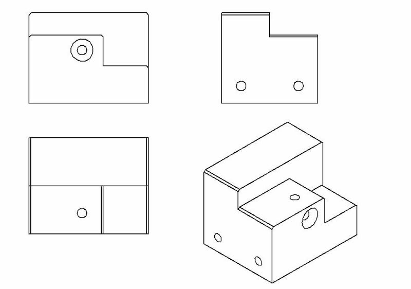
Engineering Drawing Tutorials / Orthographic Drawing solution. (T 6.8
Web in this video, i have explained how to draw an orthographic view of an object from an isometric view. Web welcome back, engineering enthusiasts! Web orthographic projections close orthographic projection a 2d drawing of a 3d object. A complete understanding of the object should be possible from the drawing. Web also called orthographic projection, orthographic drawings present different perspective.
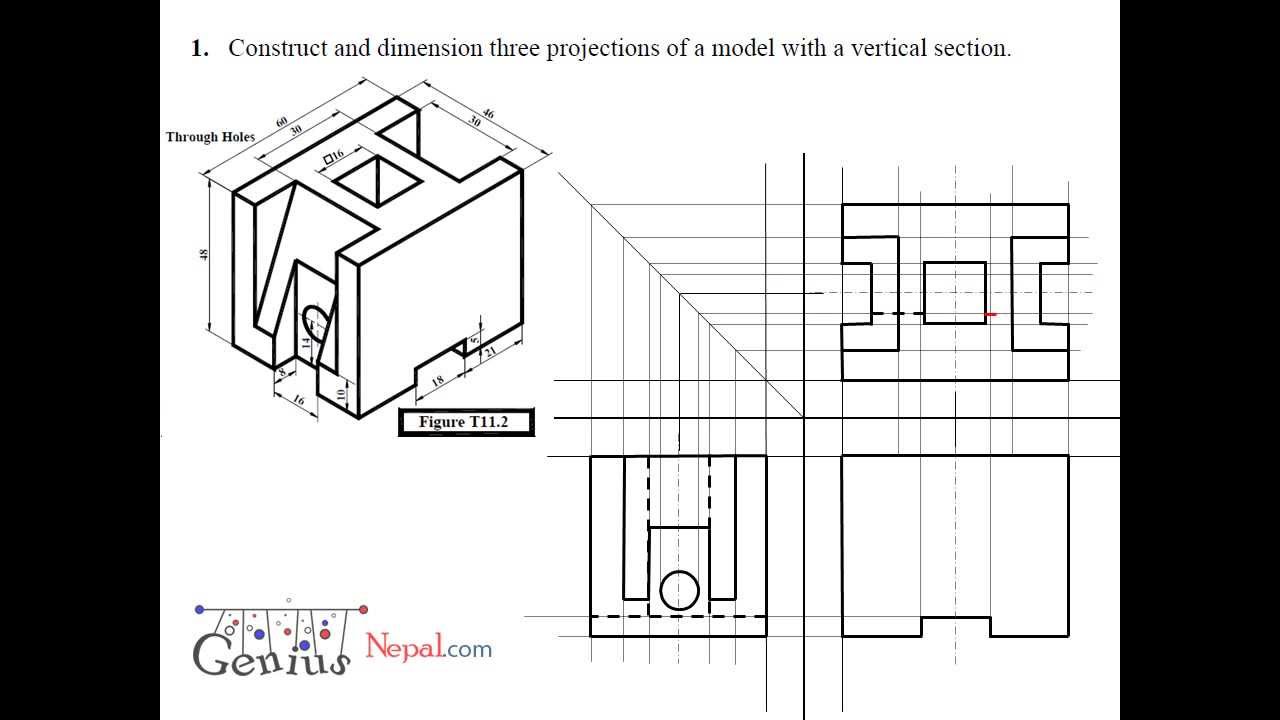
Engineering Drawing Tutorials/Orthographic and sectional views ( T 11.2
Now, since we’re drawing on paper we can’t quite make it 3d, so we call it an isometric drawing. This kind of representation allows avoiding any kind of distortion of lengths. Using the auxiliary view allows for. Web in this engineering drawing course, we delve into the fundamental principles and techniques essential for communicating complex designs. Geometrical figures are in.
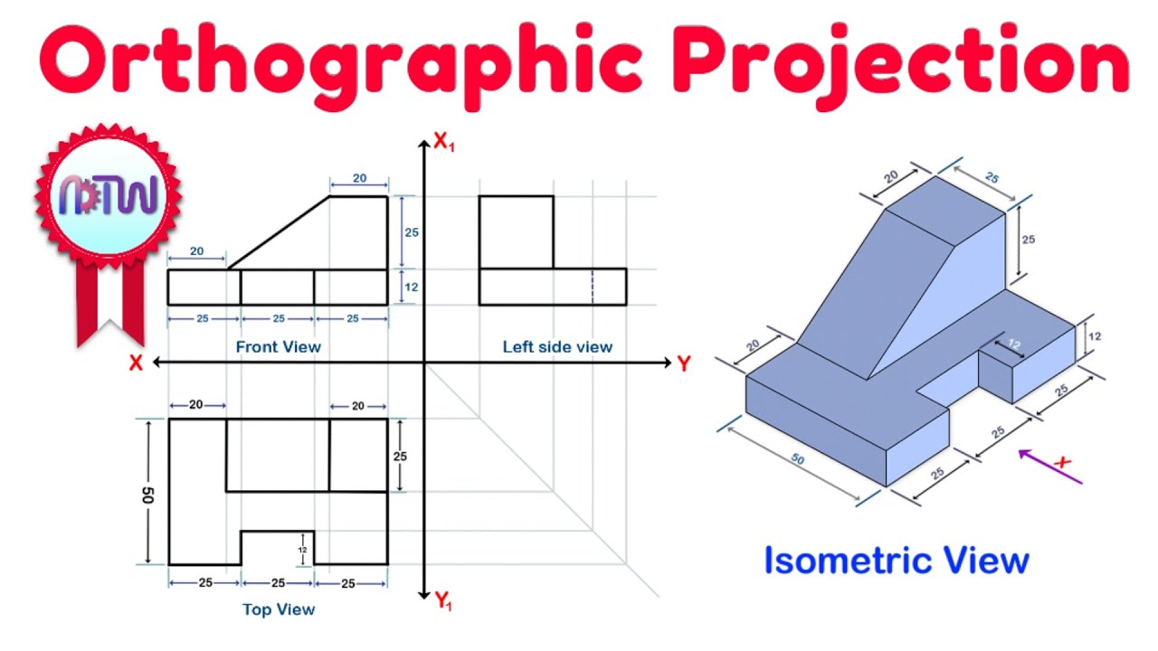
Orthographic Projection from isometric view in Engineering drawing
The most commonly used views are top. Orthographic projection is a form of parallel projection in which the top, front, and side. Web today, we are going to learn about orthographic views and why orthographic drawings are important in engineering. Web understand what orthographic drawing is by learning its definition and reviewing orthographic drawing examples. Using the auxiliary view allows.
How to create a 3D model from orthogonal projection (Orthographic
For example, an orthographic projection of a house typically. An auxiliary view is an orthographic view that is projected into any plane other than one of the six primary views. Are working drawings close working drawing an accurate line drawing to show the back and front views of a. In this comprehensive tutorial, we delve into the art of creating.

Engineering Drawing Tutorials / Orthographic Drawing with Sectional
(1) visible lines, (2) hidden lines, (3) center. Orthographic projection is a necessary component of technical drawing and helps provide useful. When multiple edges project to the same line on the drawing, the line type is determined by the following precedence: Geometrical figures are in two dimensions, hence they may be drawn to their actual sizes and shapes on a.

ISOMETRIC TO ORTHOGRAPHIC PROJECTION SUM NO 1 TECHNICAL DRAWING
Web right side of front view. Imagine slicing the object in the middle (figure 9): Web in this engineering drawing course, we delve into the fundamental principles and techniques essential for communicating complex designs. Web engineering drawing is the fundation of all engineering. Web in this video, i have explained how to draw an orthographic view of an object from.
ORTHOGRAPHIC PROJECTION IN ENGINEERING DRAWING YouTube
Web any engineering drawing should show everything: Orthographics are also called engineering drawings or plan views. These views are typically used when an object contains some sort of inclined plane. Web today, we are going to learn about orthographic views and why orthographic drawings are important in engineering. Web an engineering drawing is a type of technical drawing that is.

ORTHOGRAPHIC PROJECTION IN ENGINEERING DRAWING YouTube
Learn about first and third angle projections. Orthographic drawings are also known as multiviews. A dimension listed on an engineering drawing is known as the _______ _______. Orthographic projection is a necessary component of technical drawing and helps provide useful. Orthographics are also called engineering drawings or plan views.
From The Intro To Engineering & Design Curriculum By Paxton/Patterson Colleg.
This spatial visualization skill is different from our last activity, during which we worked on representing objects. Draw the following lines with 100 mm len gth. Web in this engineering drawing course, we delve into the fundamental principles and techniques essential for communicating complex designs. Orthographic projection is a form of parallel projection in which the top, front, and side.
Web Understand What Orthographic Drawing Is By Learning Its Definition And Reviewing Orthographic Drawing Examples.
Orthographic drawings are also known as multiviews. In isometric projection, the most commonly used form of axonometric projection in engineering drawing, the direction of viewing is such that the three axes of space appear equally foreshortened, and there is a common angle of 120° between them. Using the auxiliary view allows for. Web in other words, equal distances do not appear equal on a perspective drawing.
Geometrical Figures Are In Two Dimensions, Hence They May Be Drawn To Their Actual Sizes And Shapes On A Sheet Of Paper As It Is Also In Two Dimensions.
Make a the lowest point of the drawing. Web today, we are going to learn about orthographic views and why orthographic drawings are important in engineering. An auxiliary view is an orthographic view that is projected into any plane other than one of the six primary views. In this comprehensive tutorial, we delve into the art of creating flawless isometric views using orthographic projecti.
Now, Since We’re Drawing On Paper We Can’t Quite Make It 3D, So We Call It An Isometric Drawing.
Web engineering drawing is the fundation of all engineering. Do not dimension the drawing. From mastering orthographic projection to honing your skills in dimensioning, embark on a journey where lines, curves, and dimensions converge to bring ideas to life. An orthographic view or orthographic projection is a way of representing a 3d object in 2 dimensions.