P And Id Drawings
P And Id Drawings - The shapes in this legend are representative of the functional relationship between piping, instrumentation, and system equipment units. All components are represented using various p&id symbols. Web a piping and instrumentation diagram displays the piping components (for example equipment, valves, reducers and so on) of an actual physical process flow and is often used in the engineering projects, such as setting up steam boilers, heat exchangers, electric boilers and more. Web a p&id drawing, aka piping and instrument diagram, is a drawing that explains a physical process with the help of pipelines and other instruments present in the particular workflow or system. Process piping, sizes and identification. Web what is a p&id drawing? It shows the equipment used in the process, and all of the signals required to measure and control the process. 357k views 3 years ago basic instrumentation through animation. Web the p&id drawing is usually used in the process industry and engineering field. It is also known as pefs (process engineering flow scheme).
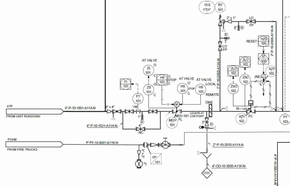
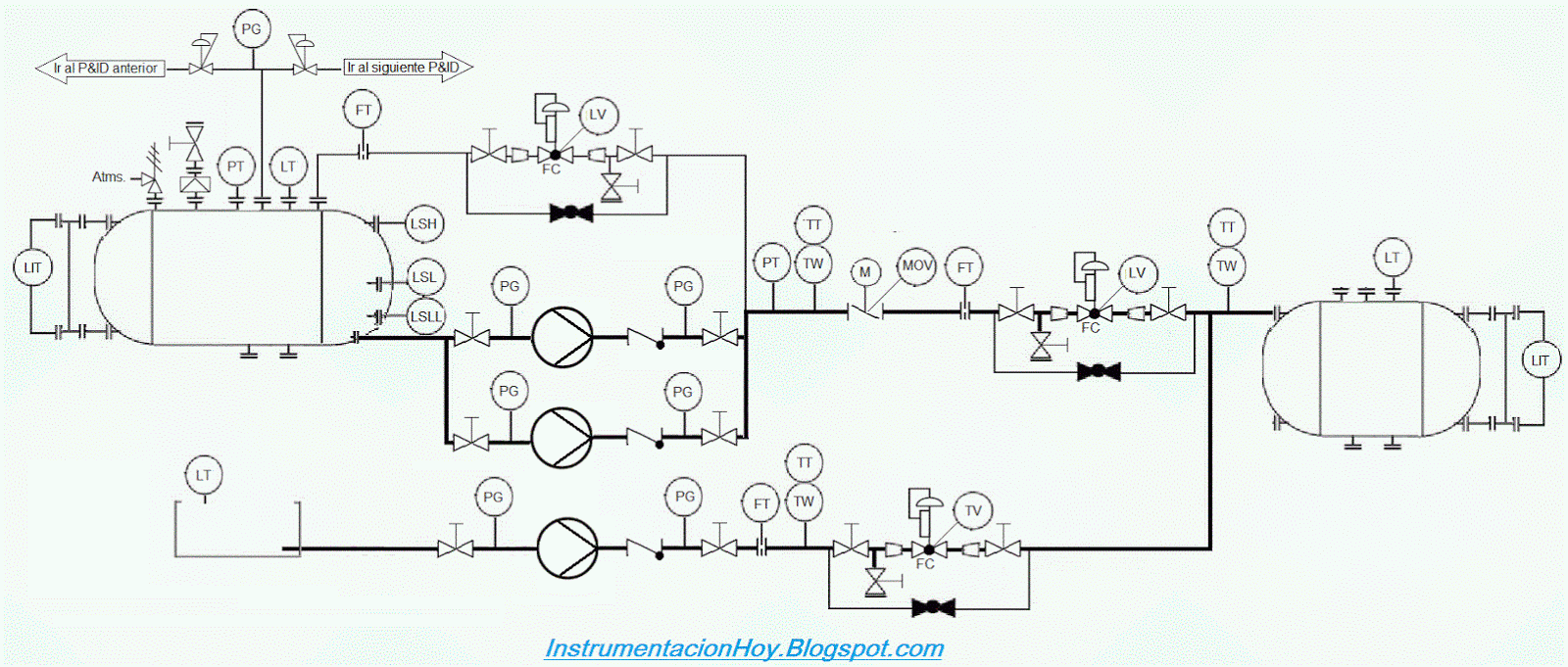
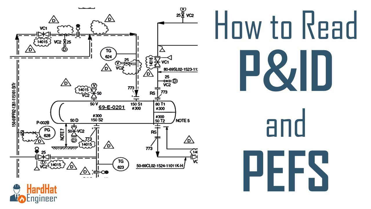
Web the p&id drawing is usually used in the process industry and engineering field. You may want to review a p&id symbols legend to ensure that you’re using the correct shapes in an appropriate context. P&id is more complex than pfd and includes lots of details. It serves as a vital tool in the process industry, forming the backbone of the design phase and providing a detailed layout of the plant's process. Web in this video, you will learn the basics of piping and instrumentation diagrams (also called p&id drawings).#pipingandinstrumentation #processcontrol #instru. Web p and id (piping and instrumentation diagram) is a schematic representation of a process system in the oil and gas, chemical, and other manufacturing industries. Web you will learn how to read p&id and pefs with the help of the actual plant drawing. Web the piping and instrumentation diagram (p&id) is a graphical representation of the actual process plant using various symbols that represent actual equipment. It includes all piping, instruments, valves, and equipment the system consists of. All valves and their identifications.
It serves as a vital tool in the process industry, forming the backbone of the design phase and providing a detailed layout of the plant's process. As this diagram covers many types of diagrams as the variety in industries is vast, many symbols are required. All components are represented using various p&id symbols. A p&id uses simple graphics to represent complex processes and convey the flow of material through a process. Select, copy and paste the components you want to use. Web piping and instrumentation diagrams, or p&ids, are used to create important documentation for process industry facilities. Web in this video, you will learn the basics of piping and instrumentation diagrams (also called p&id drawings).#pipingandinstrumentation #processcontrol #instru. P&id diagrams are made with specific and standard shapes and symbols. Web the p&id drawing is usually used in the process industry and engineering field. Web a piping and instrumentation diagram, also called p&id, is a diagram used to show a graphical display of a complete system.
Learn How to Read P&ID Drawings A Complete Guide (2023)
It shows the equipment used in the process, and all of the signals required to measure and control the process. How to read a p&id? Web you will learn how to read p&id and pefs with the help of the actual plant drawing. Web abbreviated as p&id, a piping and instrumentation diagram is an articulate drawing of a processing plan.
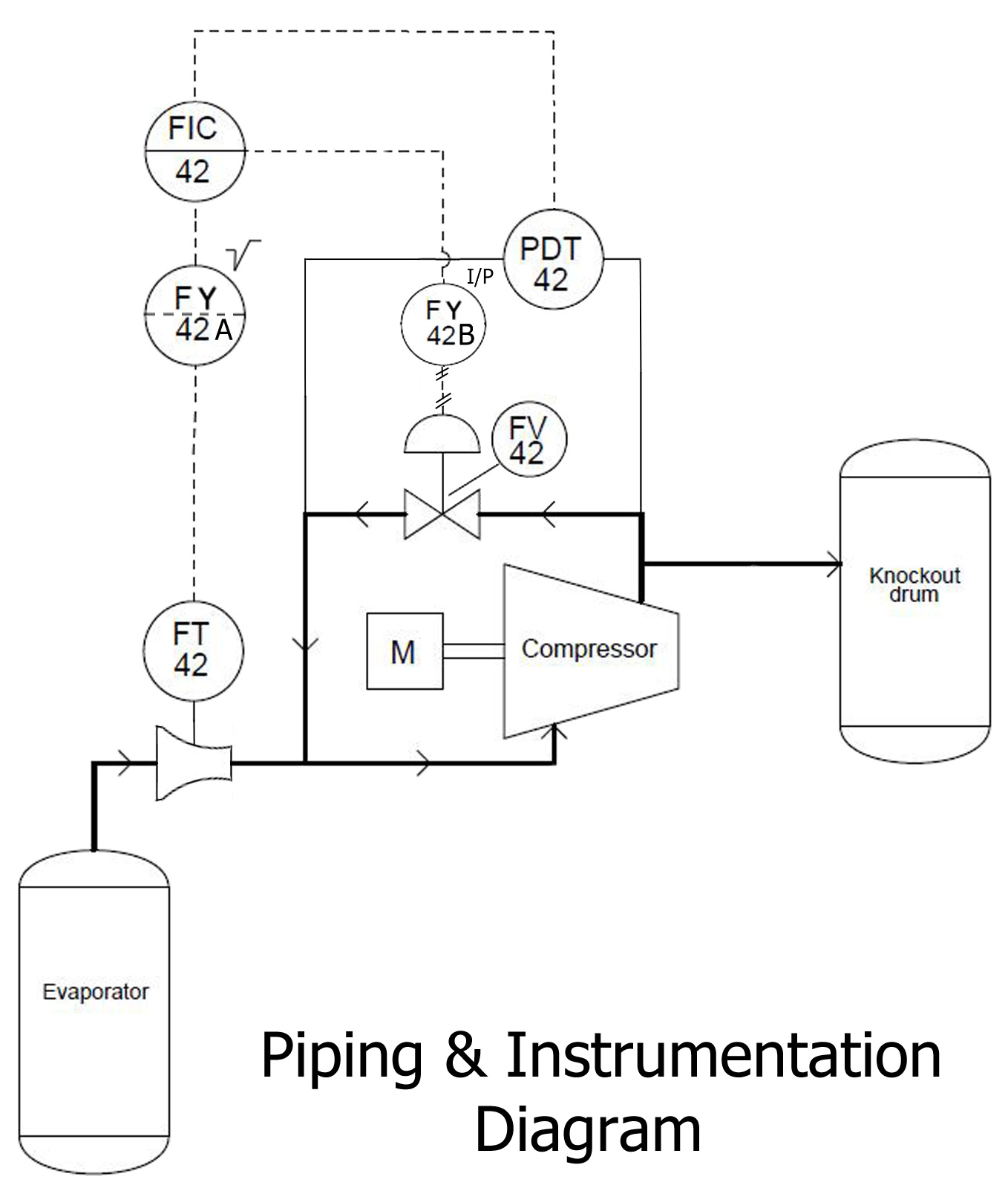
P&ID EXAMPLE
Luffy, a boy whose body gained the properties of rubber after unintentionally eating a devil fruit, is inspired by his childhood idol, the powerful pirate red haired shanks, to set off on a journey from the east blue sea to find the legendary one piece treasure and proclaim him. These diagrams use various symbols to represent the different components and.

How to Read and Interpret Piping and Instrumentation Diagrams (P&ID
Web a piping and instrumentation diagram (p&id or pid) is a detailed diagram in the process industry which shows the piping and process equipment together with the instrumentation and control devices. Want to make a p&id of your own? Web a piping and instrumentation diagram, also called p&id, is a diagram used to show a graphical display of a complete.

Read P&ID Diagram. P&ID Drawings Explained. Read Piping
To read our blog on this. Web a p&id or process and instrumentation diagram provides a detailed graphical representation of the actual process system that includes the piping, equipment, valves, instrumentation, and other process components in the system. P&id is short for “piping and instrumentation diagram”. It serves as a vital tool in the process industry, forming the backbone of.

P & ID Diagram. How To Read P&ID Drawing Easily. Piping
Web a p&id or process and instrumentation diagram provides a detailed graphical representation of the actual process system that includes the piping, equipment, valves, instrumentation, and other process components in the system. Web what is a p&id drawing? It shows the equipment used in the process, and all of the signals required to measure and control the process. Process piping,.
How to Read P&ID Drawing A Complete Tutorial YouTube
It is a detailed diagram in the process industry that shows all piping including physical sequences of branches, reducers, valves, equipment, instrumentation and control interlocks. Web abbreviated as p&id, a piping and instrumentation diagram is an articulate drawing of a processing plan that entails the piping and process equipment with its instrumentation and control machinery. Web the piping and instrumentation.
What is P&ID? (Piping and Instrumentation Diagram)? Synergy Codes
Luffy, a boy whose body gained the properties of rubber after unintentionally eating a devil fruit, is inspired by his childhood idol, the powerful pirate red haired shanks, to set off on a journey from the east blue sea to find the legendary one piece treasure and proclaim him. Web a piping and instrumentation diagram displays the piping components (for.

Learn How to Read P&ID Drawings A Complete Guide (2023)
It is a detailed diagram in the process industry that shows all piping including physical sequences of branches, reducers, valves, equipment, instrumentation and control interlocks. Web piping and instrumentation diagrams, or p&ids, are used to create important documentation for process industry facilities. P&id is more complex than pfd and includes lots of details. It displays the piping and associated parts.
How to Read a P&ID Drawing Quickly and Easily Edraw Max
Process piping, sizes and identification. It is also known as pefs (process engineering flow scheme). As this diagram covers many types of diagrams as the variety in industries is vast, many symbols are required. Web what is a p&id drawing? P&id is short for “piping and instrumentation diagram”.

Piping and Instrumentation Documents Instrumentation Tools
When you have the right tools on hand, it’s time to begin. Web make your own p&id diagrams with this free online drawing tool. These diagrams use various symbols to represent the different components and instruments involved in the process. A link to download this p&id is given at the end of the page. Log in to your google account.
All Valves And Their Identifications.
It displays the piping and associated parts of a physical process flow. Web p&id stands for piping and instrumentation diagram or drawing. Through a p&id, you can get the following information: Web a p&id or process and instrumentation diagram provides a detailed graphical representation of the actual process system that includes the piping, equipment, valves, instrumentation, and other process components in the system.
Web P And Id (Piping And Instrumentation Diagram) Is A Schematic Representation Of A Process System In The Oil And Gas, Chemical, And Other Manufacturing Industries.
Web in this video, you will learn the basics of piping and instrumentation diagrams (also called p&id drawings).#pipingandinstrumentation #processcontrol #instru. All components are represented using various p&id symbols. Select, copy and paste the components you want to use. Web a piping and instrumentation diagram (p&id) is a comprehensive schematic that illustrates the functional relationship of piping, instrumentation, and system equipment components within a process plant.
In The Engineering And Manufacturing Field, P&Id Drawings Are Highly Relevant As They Can Help Develop The Operation.
It is also called as mechanical flow diagram (mfd). A link to download this p&id is given at the end of the page. Web p&ids are a schematic illustration of the functional relationship of piping, instrumentation and system equipment components used in the field of instrumentation and control or automation. Process piping, sizes and identification.
Web To Draw A Piping And Instrumentation Diagram, You’ll Need A Basic Understanding Of What A P&Id Is.
They are typically created by engineers who are designing a manufacturing process for a physical plant. You may want to review a p&id symbols legend to ensure that you’re using the correct shapes in an appropriate context. Web what is a p&id drawing? Web a piping and instrumentation diagram (p&id or pid) is a detailed diagram in the process industry which shows the piping and process equipment together with the instrumentation and control devices.