Phantom Lines In Engineering Drawing
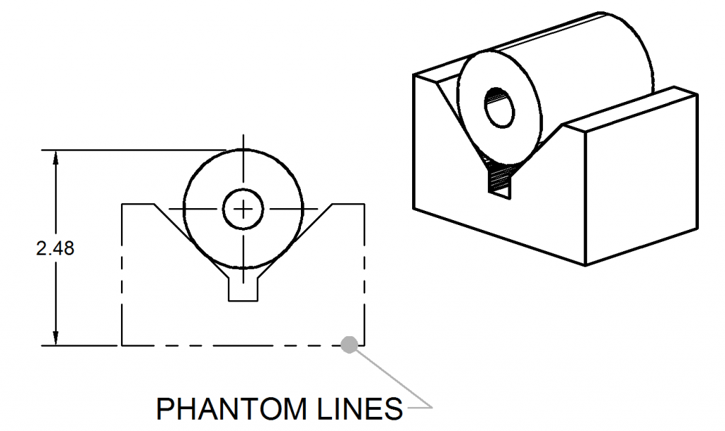
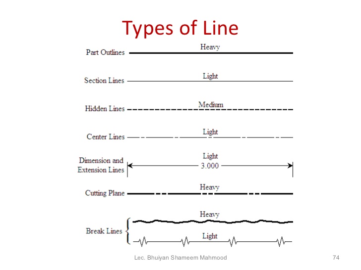
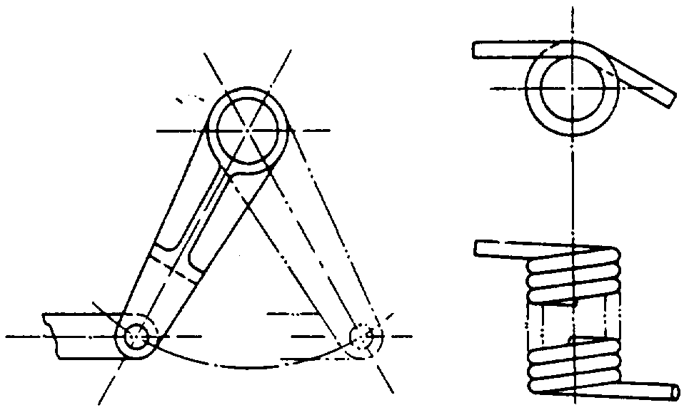
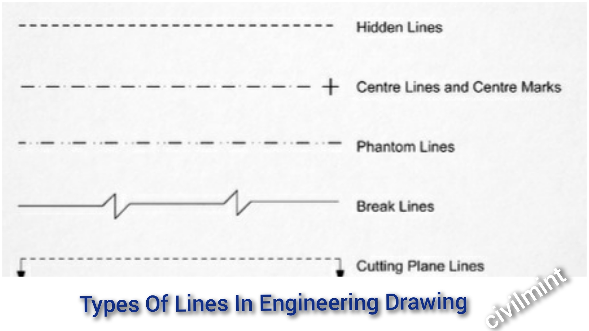
Phantom Lines In Engineering Drawing - Some lines are complete, and others are broken. Web certain features on a engineering drawing requires specific ways of indication. These drawings are essentially the blueprints or plans for manufacturing a wide array of products and structures. Standard lines have been developed so that every drawing or sketch conveys the same meaning to everyone. You can also view this article in slides and download in pdf format. These lines consist of long dashes alternated with pairs of small dashes. From part navigator, select the drawing node > rmb > update. This drawing of a doorstop illustrates the use of the common line types. Web the part in one position is drawn in full lines, while in the alternate position it is drawn in phantom lines. Web phantom lines represent the outline of an adjacent part, show alternate positions of a moving part, or replace repetitive details such as gear teeth and threads break lines
The alphabet of lines and the approximate dimensions used to create different line types, are referred to. Selected component will be displayed. Section lines are generally drawn at a 45° angle. First go to sketch, draw your line (s). Drawn to indicate the exact geometric centre of the assembly. Web certain features on a engineering drawing requires specific ways of indication. Web the part in one position is drawn in full lines, while in the alternate position it is drawn in phantom lines. This type of line in engineering drawings serves the following purposes: Web (phantom line type) section lines: Also used to indicate a break when the nature of the object makes the use of the conventional type of break unfeasible.
In edit object display dialog, set line font to phantom, ok. Types of lines include the following: Drawn to indicate the exact geometric centre of the assembly. It can also be used to show adjacent objects or features. These drawings are essentially the blueprints or plans for manufacturing a wide array of products and structures. These features are typically inside the object or obscured by other surfaces. Web certain features on a engineering drawing requires specific ways of indication. Web phantom lines represent the outline of an adjacent part, show alternate positions of a moving part, or replace repetitive details such as gear teeth and threads break lines Standard lines have been developed so that every drawing or sketch conveys the same meaning to everyone. From part navigator, select the drawing node > rmb > update.
Phantom Lines ToolNotes
Used to indicate where the cutting plane cuts the material. Some lines are complete, and others are broken. From part navigator, select the drawing node > rmb > update. Standard lines have been developed so that every drawing or sketch conveys the same meaning to everyone. Web standard engineering drawing line types.

Type of Line used in (ED) Engineering Drawing Phantom line hidden
The alphabet of lines and the approximate dimensions used to create different line types, are referred to. Section lines are thin and the symbols (type of lines) are chosen according to the material of the object. Web phantom lines represent the outline of an adjacent part, show alternate positions of a moving part, or replace repetitive details such as gear.
Phantom line gages as datum "features"? Drafting Standards, GD&T
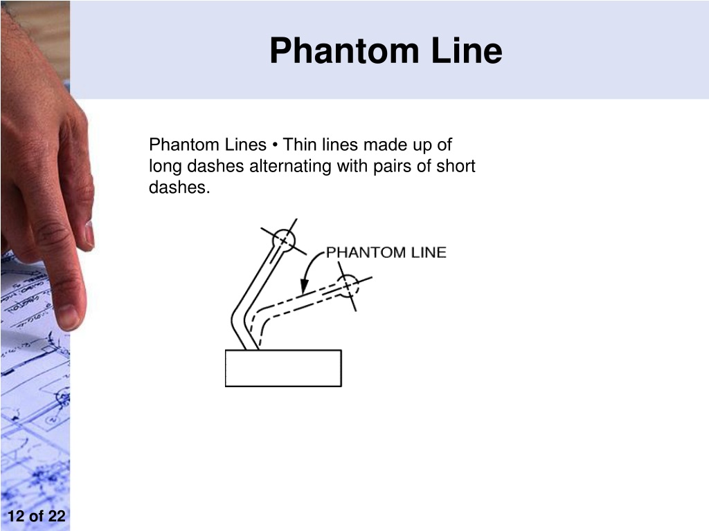
It can also be used to show adjacent objects or features. In order to convey that meaning, the lines used in technical drawings have both a definite pattern and a definite thickness. For example, holes require center lines to identify the center and show that it is round. Phantom lines are drawn as thin, alternating long dashes separated by two.
PPT Engineering Drawing PowerPoint Presentation, free download ID
Web phantom lines are very useful in the engineering drawing. The long dashes may vary in length, depending on the size of the drawing. Phantom lines are drawn as thin, alternating long dashes separated by two short dashes. Web certain features on a engineering drawing requires specific ways of indication. Phantom lines are used to indicate imaginary features.

How to add phantom/hidden lines on drawings? GrabCAD Tutorials
Army research, development and engineering center (ardec), attn: Also used to indicate a break when the nature of the object makes the use of the conventional type of break unfeasible. Web standard engineering drawing line types. The long dashes may vary in length, depending on the size of the drawing. Web in this article, you will learn about the types.

Types of Lines Engineering Drawing MechGate YouTube
Section lines are thin and the symbols (type of lines) are chosen according to the material of the object. First go to sketch, draw your line (s). These drawings are essentially the blueprints or plans for manufacturing a wide array of products and structures. Web in this lecture we will learn what is phantom line and usage of phantom line.
Phantom Lines ToolNotes
The long dashes may vary in length, depending on the size of the drawing. Web the part in one position is drawn in full lines, while in the alternate position it is drawn in phantom lines. In order to convey that meaning, the lines used in technical drawings have both a definite pattern and a definite thickness. Or you could.
Different Types Of Lines Engineering Drawing
You can also view this article in slides and download in pdf format. These features are typically inside the object or obscured by other surfaces. Web standard engineering drawing line types. First go to sketch, draw your line (s). Web edit object display (ctrl+j), select component from assembly navigator.
Line Conventions
Web the alphabet of lines is a set of standard line types established by the american national standards institute (ansi) for technical drawing. Army research, development and engineering center (ardec), attn: This drawing of a doorstop illustrates the use of the common line types. Web edit object display (ctrl+j), select component from assembly navigator. The alphabet of lines and the.
Types Of Lines In Engineering Drawing
From part navigator, select the drawing node > rmb > update. A variety of line styles graphically represent physical objects. Some lines are complete, and others are broken. You can also view this article in slides and download in pdf format. Web (phantom line type) section lines:
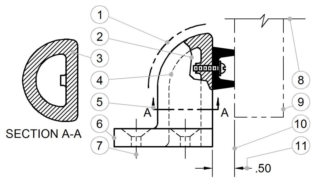
Web Phantom Lines Are Used To Show Repeated Detail.
Standard lines have been developed so that every drawing or sketch conveys the same meaning to everyone. Used to indicate where the cutting plane cuts the material. Hidden detail are shown with a certain line type to avoid confusion with visible edges. Web the alphabet of lines is a set of standard line types established by the american national standards institute (ansi) for technical drawing.
For Example, Holes Require Center Lines To Identify The Center And Show That It Is Round.
Proposed changes by dod activities must be submitted to the dod adopting activity: This type of line in engineering drawings serves the following purposes: Web (phantom line type) section lines: The alphabet of lines and the approximate dimensions used to create different line types, are referred to.
Web Phantom Lines Represent The Outline Of An Adjacent Part, Show Alternate Positions Of A Moving Part, Or Replace Repetitive Details Such As Gear Teeth And Threads Break Lines
Phantom lines are used to indicate imaginary features. It can also be used to show adjacent objects or features. Phantom lines are also used to indicate a break when the nature of the object makes the use of the conventional type of break unfeasible. The long dashes may vary in length, depending on the size of the drawing.
Selected Component Will Be Displayed.
You can also view this article in slides and download in pdf format. Section lines are thin and the symbols (type of lines) are chosen according to the material of the object. For example, they are used to indicate the alternate positions of moving parts, and adjacent positions of related parts. Web standard engineering drawing line types.