Pid Drawing
Pid Drawing - P&id is a schematic drawing that gives a primary visual representation of a process control system. With ignition’s perspective module, any information about a process or business system can be in the palm of our hand. On the drawing page, select the shape to which you would like to add data. P&id symbols, which stand for piping and instrumentation diagram symbols, are graphical representations used in engineering and process industries to depict the process flow, equipment, instrumentation, and control systems of a system or a plant. With visual paradigm online, you don't need to start each p&id from scratch because a rich set of piping. Because using simplified and united symbols and vivid equipment icons, people are more likely to know the p&id drawings and what they represent. Do one of the following: A variety of options appear here; Web here, i have tried to explain p&id and pefs in an easy way. Web a piping and instrumentation diagram (p&id) is defined as follows:
Therefore, if the tank reaches 90% of its total capacity. Since p&ids are graphic representations of processes, they have some inherent limitations. On the drawing page, select the shape to which you would like to add data. Click in each shape data field, and type or select a value. Because using simplified and united symbols and vivid equipment icons, people are more likely to know the p&id drawings and what they represent. The tag number helps in identifying the device, whereas the line is the location indicator. P&id symbols, which stand for piping and instrumentation diagram symbols, are graphical representations used in engineering and process industries to depict the process flow, equipment, instrumentation, and control systems of a system or a plant. No matter how intricate your process or system, lucidchart can help you build, style, edit, and share your diagram as you please. The piping and instrumentation diagram is also known as the process engineering flow scheme, pefs. P&id is a schematic drawing that gives a primary visual representation of a process control system.
No matter how intricate your process or system, lucidchart can help you build, style, edit, and share your diagram as you please. It is the basic training document to explain the process details to operation guys, field engineers, and maintenance professionals. Lines are classified into different types, each describing the device's location with respect to the field. Web a piping and instrumentation diagram (p&id) is a comprehensive schematic that illustrates the functional relationship of piping, instrumentation, and system equipment components within a process plant. Select, copy and paste the components you want to use. Click in each shape data field, and type or select a value. The tag number helps in identifying the device, whereas the line is the location indicator. More fully developed piping and instrumentation diagrams (p&ids) are shown in a p&id. Customize existing components and make new ones. P&ids are used to develop guidelines and standards for facility operation;
How to Read P&ID Drawing A Complete Tutorial YouTube
A diagram which shows the interconnection of process equipment and the instrumentation used to control the process. More fully developed piping and instrumentation diagrams (p&ids) are shown in a p&id. Web easily manage, update, and share your p&id drawing. Web once the p&id shapes are available to you, simply drag the necessary shapes onto the canvas and configure them by.
P&ID Symbol Diagram Basics Functional Identification and Naming
P&id symbols, which stand for piping and instrumentation diagram symbols, are graphical representations used in engineering and process industries to depict the process flow, equipment, instrumentation, and control systems of a system or a plant. Web once the p&id shapes are available to you, simply drag the necessary shapes onto the canvas and configure them by clicking the context panel.
P&ID Valve Symbols How to read them on most common control valves
A storage tank is filled with condensed products formed via the cstr in example 1. Since p&ids are graphic representations of processes, they have some inherent limitations. Web in this video, you will learn the basics of piping and instrumentation diagrams (also called p&id drawings).#pipingandinstrumentation #processcontrol #instru. A diagram which shows the interconnection of process equipment and the instrumentation used.

How to Read and Interpret Piping and Instrumentation Diagrams (P&ID
No matter how intricate your process or system, lucidchart can help you build, style, edit, and share your diagram as you please. Create the full list of instruments and equipment required for the process. More fully developed piping and instrumentation diagrams (p&ids) are shown in a p&id. Web on the data tab, click shape data window. It shows the essential.

Learn How to Read P&ID Drawings A Complete Guide (2023)
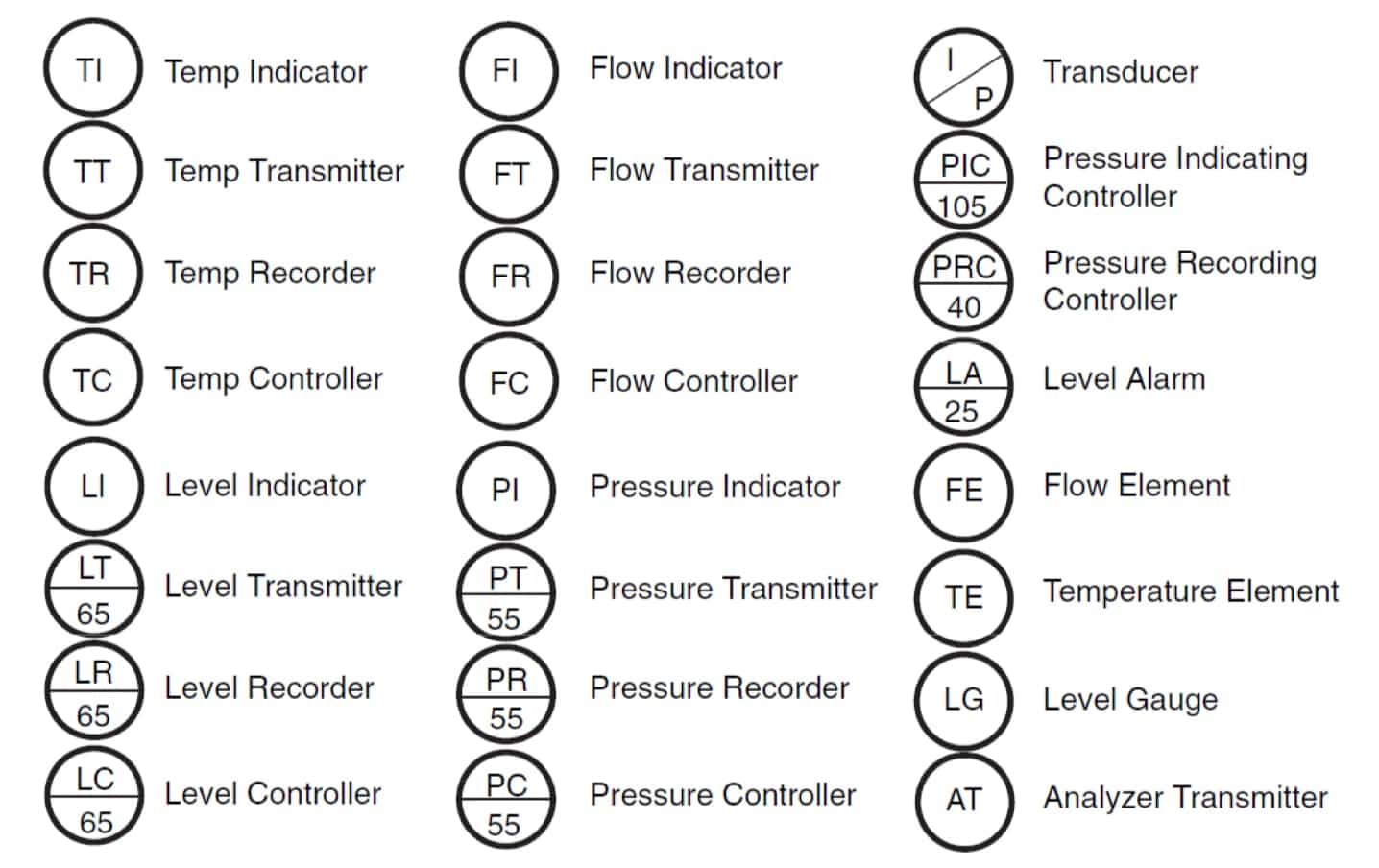
These symbols are essential for engineers, operators, and maintenance personnel to. We've broken them down into seven main groups: The symbology for the identification of the measurement and control instrumentation on the flow and process diagrams and on the p&id (piping & instrument diagram), commonly called p&i (piping & instrumentation), is generally compliant with the standard isa (instrumentation society of.
How to Read a P&ID Drawing Quickly and Easily Edraw Max
With visual paradigm online, you don't need to start each p&id from scratch because a rich set of piping. To add the property set to shapes on a drawing, select the shapes. Create the full list of instruments and equipment required for the process. Piping and instrumentation diagrams, or p&ids, are used to create important documentation for process industry facilities..

Piping and Instrumentation Documents Instrumentation Tools
Web make your own p&id diagrams with this free online drawing tool. Click in each shape data field, and type or select a value. Web a piping and instrumentation diagram (p&id) is defined as follows: Select, copy and paste the components you want to use. With visual paradigm online, you don't need to start each p&id from scratch because a.

P & ID Diagram. How To Read P&ID Drawing Easily. Piping
Web here, i have tried to explain p&id and pefs in an easy way. Without a doubt, visual paradigm online is the best p&id software to create schematics for the process industry. In the process industry, a standard set of symbols is used to prepare drawings of processes. Edrawmax online helps designers and engineers to create p&id drawings fast and.
Learn How to Read P&ID Drawings A Complete Guide (2023)
In the process industry, a standard set of symbols is used to prepare drawings of processes. Web a piping and instrumentation diagram (p&id) is defined as follows: Web on the data tab, click shape data window. Web easily manage, update, and share your p&id drawing. The piping and instrumentation diagram is also known as the process engineering flow scheme, pefs.

P&ID Drawings 101 Corso Systems
Only a few steps to follow to create a p&id diagram, but one who does it should know well knowledge about the plant process. Because using simplified and united symbols and vivid equipment icons, people are more likely to know the p&id drawings and what they represent. More fully developed piping and instrumentation diagrams (p&ids) are shown in a p&id..
The Instrument Symbols Used In These Drawings Are Generally Based On.
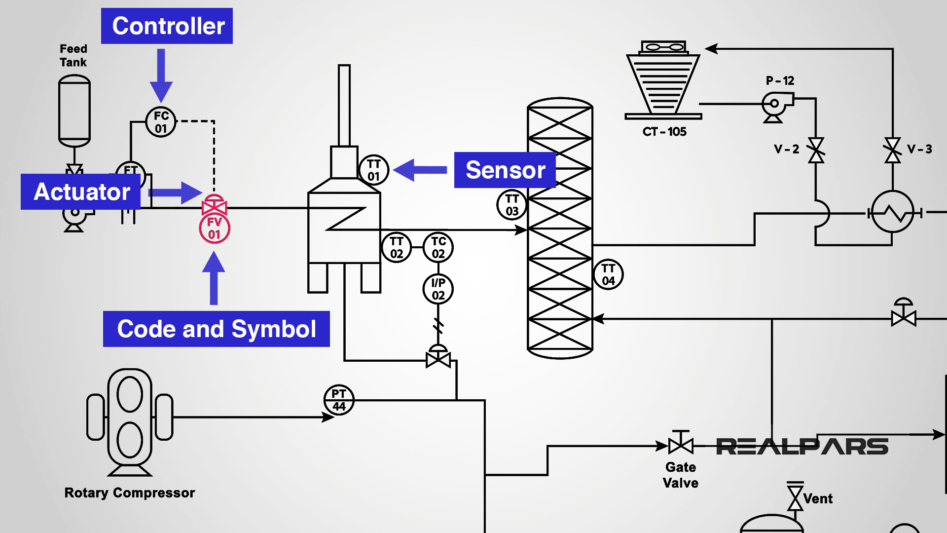
For example, a tank can be customized with various roof types, and users can toggle between hiding and showing the stump. Web all the instruments in a p&id are marked by a circle with an assigned tag number and line inside. A variety of options appear here; Web p&id drawings 101.
Check The Symbols Used For Each Equipment From The Library.
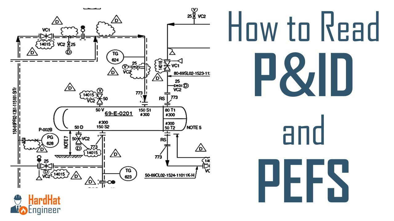
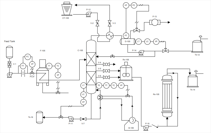
Web easily manage, update, and share your p&id drawing. To add the property set to shapes on a drawing, select the shapes. We live in an exciting time. You will learn how to read p&id and pefs with the help of the actual plant drawing.
Web Draw A Proper P&Id Diagram Of The Following Process:
Web a piping and instrumentation diagram (p&id) is a comprehensive schematic that illustrates the functional relationship of piping, instrumentation, and system equipment components within a process plant. Do one of the following: P&ids are used to develop guidelines and standards for facility operation; Create the full list of instruments and equipment required for the process.
Without A Doubt, Visual Paradigm Online Is The Best P&Id Software To Create Schematics For The Process Industry.
Web once the p&id shapes are available to you, simply drag the necessary shapes onto the canvas and configure them by clicking the context panel icon that appears next to the shape. Select, copy and paste the components you want to use. All the below p&id symbols are existing in the symbol library of edraw max. Web on the data tab, click shape data window.