Pipe Drawings
Pipe Drawings - Web piping isometric drawing is an isometric representation of single pipe line in a plant. 254k views 2 years ago. This is a certified workshop! If you are in the oil and gas, chemical, or manufacturing industries, you probably are looking for a straightforward way to draw piping in cad. Web of drafting abbreviations used on piping drawings. Discover the essentials of piping isometrics, including how they simplify complex piping systems for construction, maintenance, and documentation purposes. Pipe size is always written at any connecting point of isometric. Piping joint types, weld types. Web a piping isometric drawing provides all the required information like: Web the fitting, flange, and valve drawing symbols unique to isometrics are depicted.
Select all / deselect all. Web © 2024 google llc. Pipe drawings are much different from specific weld symbols but they do have a similar relationship from part to symbol. Piping isometric drawing consists of three sections. If you are in the oil and gas, chemical, or manufacturing industries, you probably are looking for a straightforward way to draw piping in cad. Piping isometric drawings are detailed technical illustrations that show a 3d view of piping systems. Web type b concrete endwalls, bill of steel for concrete pipes (pipe sizes 15 to 78, all skews, 2:1 slope) (click image to open pdf) related standard drawings. Piping and component descriptions with size, quantity, and material codes. Piping isometric drawing dimensions are always from center to center of pipe. Web piping isometric drawing is an isometric representation of single pipe line in a plant.
The drawings we often see in these fields would be orthographic views which may include top, front, right side, left side, bottom, and back views depending on what is needed to convey information. It is the most important deliverable of piping engineering department. Web what are pipeline isometric drawings? Select all / deselect all. Piping isometric drawing consists of three sections. Web of drafting abbreviations used on piping drawings. Web various symbols are used to indicate piping components, instrumentation, equipments in engineering drawings such as piping and instrumentation diagram (p&id), isometric drawings, plot plan, equipment layout, welding drawings etc. How to read isometric drawing in a piping isometrics drawing, pipe is drawn according to it’s. Piping joint types, weld types. Piping isometric drawing dimensions are always from center to center of pipe.
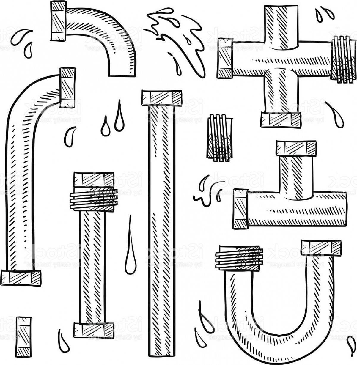
Pipe Sketch at Explore collection of Pipe Sketch
Web how to start your piping project. Pipe drawings are much different from specific weld symbols but they do have a similar relationship from part to symbol. The drawings we often see in these fields would be orthographic views which may include top, front, right side, left side, bottom, and back views depending on what is needed to convey information..
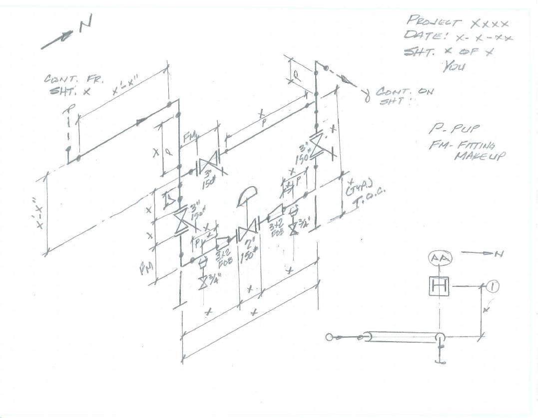
How to read iso pipe drawings perlogistics
Web easy isometric is the first pipe isometric drawing app that helps users make detailed isometric drawings in the field and without the need for tedious reference materials. Web the features of edrawmax. 1.2.4 drawing numbering commonly, with the exception of the construction isometrics, clients have drawing numbering requirements. Web drawings are engineering’s international language engineers all over the world.
Smoking pipe. Ink black and white drawing Stock Photo Alamy
Web master piping isometrics with our comprehensive guide: File numbering, which ideally should equate to table 1.2 branch connections instrument and utility air Types of drawings •process flow diagrams: Pipe size is always written at any connecting point of isometric. Web piping isometric drawing is an isometric representation of single pipe line in a plant.

Piping Design Basics Piping Isometric Drawings Piping Isometrics
Pipe drawings differ from common blueprints one would see in the construction or welding field. Piping joint types, weld types. The drawings we often see in these fields would be orthographic views which may include top, front, right side, left side, bottom, and back views depending on what is needed to convey information. Web the fitting, flange, and valve drawing.

How to read piping isometric drawing, Pipe fitter training, Watch the
Pipe drawings are much different from specific weld symbols but they do have a similar relationship from part to symbol. Pipe size is always written at any connecting point of isometric. Web what are pipeline isometric drawings? Web various symbols are used to indicate piping components, instrumentation, equipments in engineering drawings such as piping and instrumentation diagram (p&id), isometric drawings,.
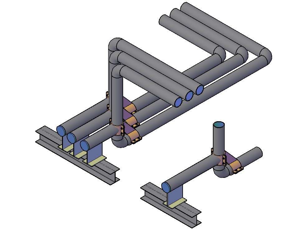
3D Pipe Drawing In AutoCAD File Cadbull
Pipe size is always written at any connecting point of isometric. Piping joint types, weld types. File numbering, which ideally should equate to table 1.2 branch connections instrument and utility air Web various symbols are used to indicate piping components, instrumentation, equipments in engineering drawings such as piping and instrumentation diagram (p&id), isometric drawings, plot plan, equipment layout, welding drawings.

How to read piping Isometric drawing YouTube
Pipe size is always written at any connecting point of isometric. There are usually five types of piping drawings that are prepared to communicate various information in a simple and easy way. Web a piping isometric drawing is a technical drawing that depicts a pipe spool or a complete pipeline using an isometric representation. Each client mandates the drawing numbering.

Sketch Pipes System Sketches, Plumbing logo, Infographic inspiration
The drawing axes of the isometrics intersect at an angle of 60°. Web piping isometric drawing is an isometric representation of single pipe line in a plant. The drawings we often see in these fields would be orthographic views which may include top, front, right side, left side, bottom, and back views depending on what is needed to convey information..

How to read piping isometric drawing pdf fleetlio
Piping isometric drawing dimensions are always from center to center of pipe. 254k views 2 years ago. Each client mandates the drawing numbering to be used. The use of coordinate and elevation callouts to determine configuration dimensions of the routed pipe is explained. Edrawmax is ideal for pip design engineers and design designers who must draw detailed pip design drawings.

Guide to Tobacco Pipes & Pipe Smoking
Piping joint types, weld types. Discover the essentials of piping isometrics, including how they simplify complex piping systems for construction, maintenance, and documentation purposes. File numbering, which ideally should equate to table 1.2 branch connections instrument and utility air 2.8k views 3 years ago mechanical. Web drawings are engineering’s international language engineers all over the world can understand them.
Pipe Drawings Differ From Common Blueprints One Would See In The Construction Or Welding Field.
How to read isometric drawing in a piping isometrics drawing, pipe is drawn according to it’s. Piping isometric drawings are detailed technical illustrations that show a 3d view of piping systems. Web of drafting abbreviations used on piping drawings. If you are in the oil and gas, chemical, or manufacturing industries, you probably are looking for a straightforward way to draw piping in cad.
Reading Tips, Symbols, And Drawing Techniques For Engineers And Piping Professionals.
Some individuals will not see these in their line of work but it is important to be aware of them. We are concluding our first pipefitter series run with a video on how to draw isometric drawings. Web the features of edrawmax. • piping size and type identified for all lines.
254K Views 2 Years Ago.
Web easy isometric is the first pipe isometric drawing app that helps users make detailed isometric drawings in the field and without the need for tedious reference materials. Web the fitting, flange, and valve drawing symbols unique to isometrics are depicted. Web © 2024 google llc. Checkout list of such symbols given below.
Types Of Drawings •Process Flow Diagrams:
There are usually five types of piping drawings that are prepared to communicate various information in a simple and easy way. Web various symbols are used to indicate piping components, instrumentation, equipments in engineering drawings such as piping and instrumentation diagram (p&id), isometric drawings, plot plan, equipment layout, welding drawings etc. Web drawings are engineering’s international language engineers all over the world can understand them. Web a piping isometric drawing is a technical drawing that depicts a pipe spool or a complete pipeline using an isometric representation.