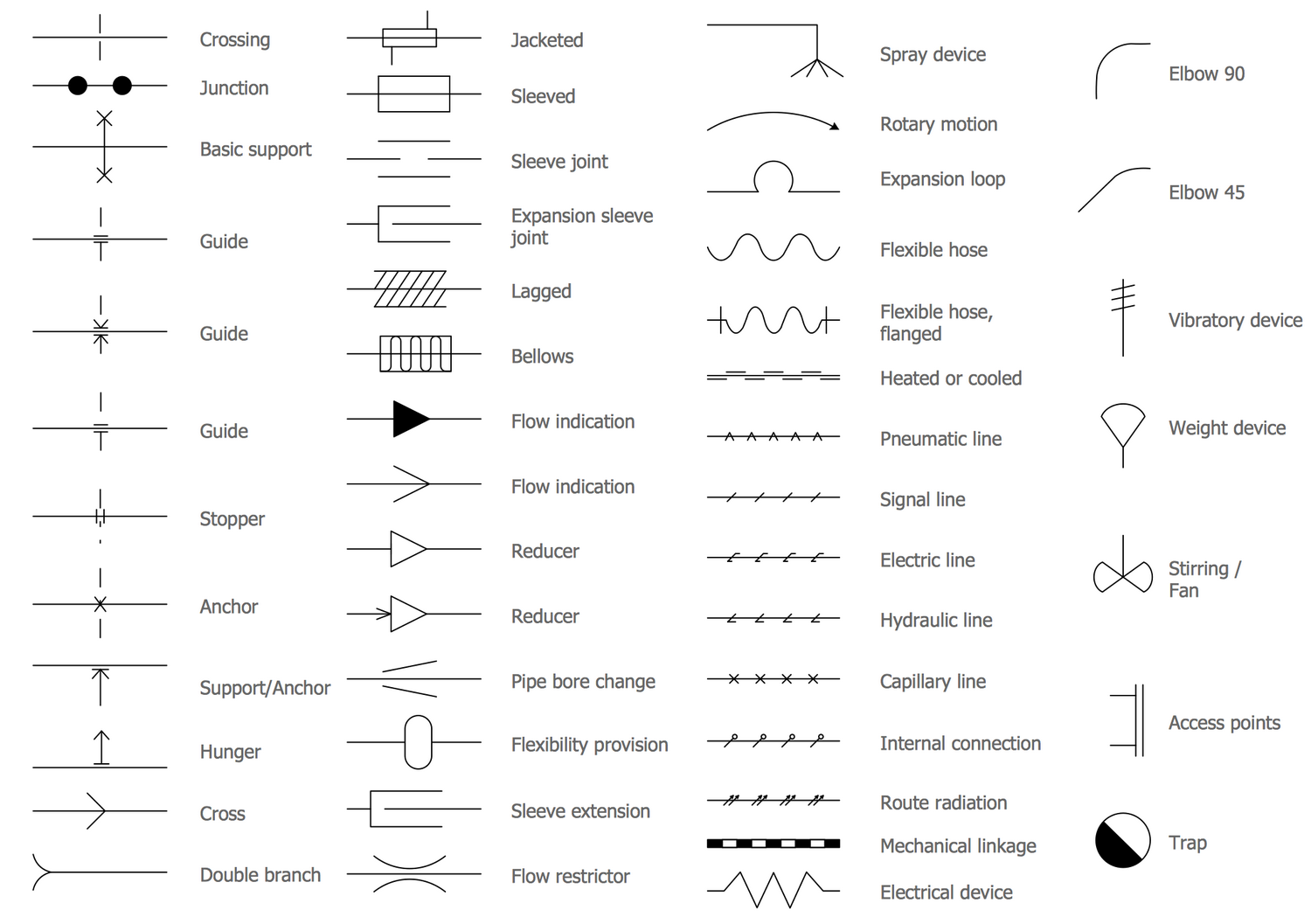
Piping Drawing Symbols
Piping Drawing Symbols - Want to design your plumbing & pipping plan? Web symbols shown on fig. These symbols are categorized under the following headings: Web piping and instrumentation diagrams (p&ids) use specific symbols to show the connectivity of equipment, sensors, and valves in a control system. Checkout list of such symbols given below. Pressure, temperature, flow, level, switches, alarms, and miscellaneous. So, not from the outside of a pipe or fitting. Web we've broken them down into seven main groups: 3 are to be combined with the appropriate symbol from fig. Web piping symbols for isometric drawings.
A pipe into a isometric view, is always drawn by a single line. These lines are the main arteries of the process system, showing the direction of flow and connections between equipment. 5 provides symbols for fans, pumps, and turbines. So, not from the outside of a pipe or fitting. Switch to mac > try it free. Just try it free now! Knowing legends and symbols that are universal for reading a piping isometric drawing is much helpful to gain info about the piping material or piping fittings that are going to be used for fabrication or construction work. How to read a piping isometric? These symbols are categorized under the following headings: Learn from this article to know everything about plumbing symbols, and how to use or create plumbing symbols.
Web more than 2000 vector piping and instrumentation diagram symbols are provided including ductwork symbols, valves, pumps, motors, blowers, chillers, tanks, logistics, production process symbols, hvac symbols, and much more. 5 provides symbols for fans, pumps, and turbines. Get the most comprehensive collection of. It also has a standard method of indication for pipe fittings, valves piping & allied items on their plans. These symbols are categorized under the following headings: Switch to mac > try it free. Web piping and instrumentation diagrams (p&ids) use specific symbols to show the connectivity of equipment, sensors, and valves in a control system. Lighter lines show connected pipe, and are not parts of the symbols. Web piping isometric drawing software is an essential tool for piping engineers and designers to create detailed isometric drawings of piping systems. The symbols are organized in sections including equipment, fire and safety, flow.
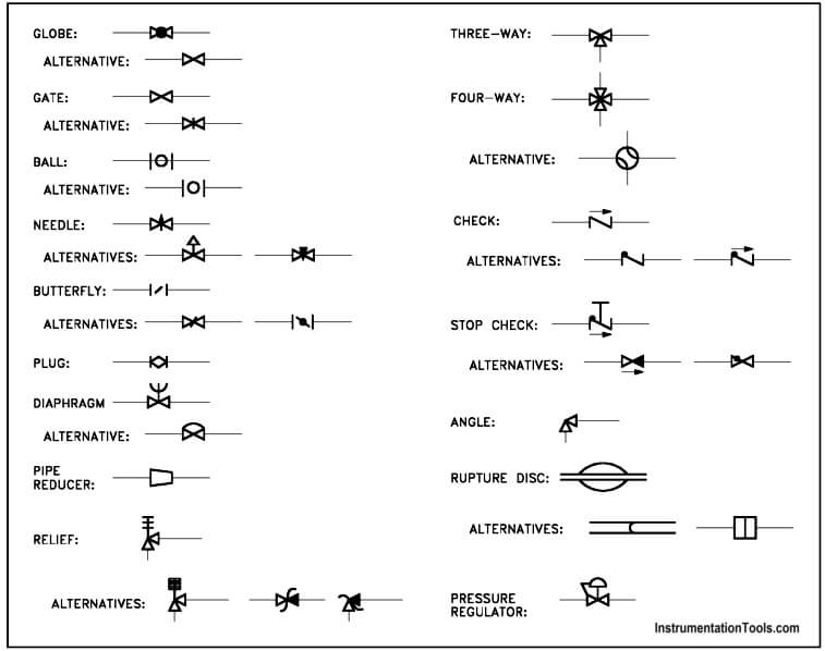
Piping and Instrumentation Symbols Instrumentation Tools
With lucidchart, it's easy to access all of the featured p&id symbols. So, not from the outside of a pipe or fitting. 3 are to be combined with the appropriate symbol from fig. Web piping and instrument diagram standard symbols detailed documentation provides a standard set of shapes & symbols for documenting p&id and pfd, including standard shapes of instrument,.
Piping Schematic Symbols Pdf
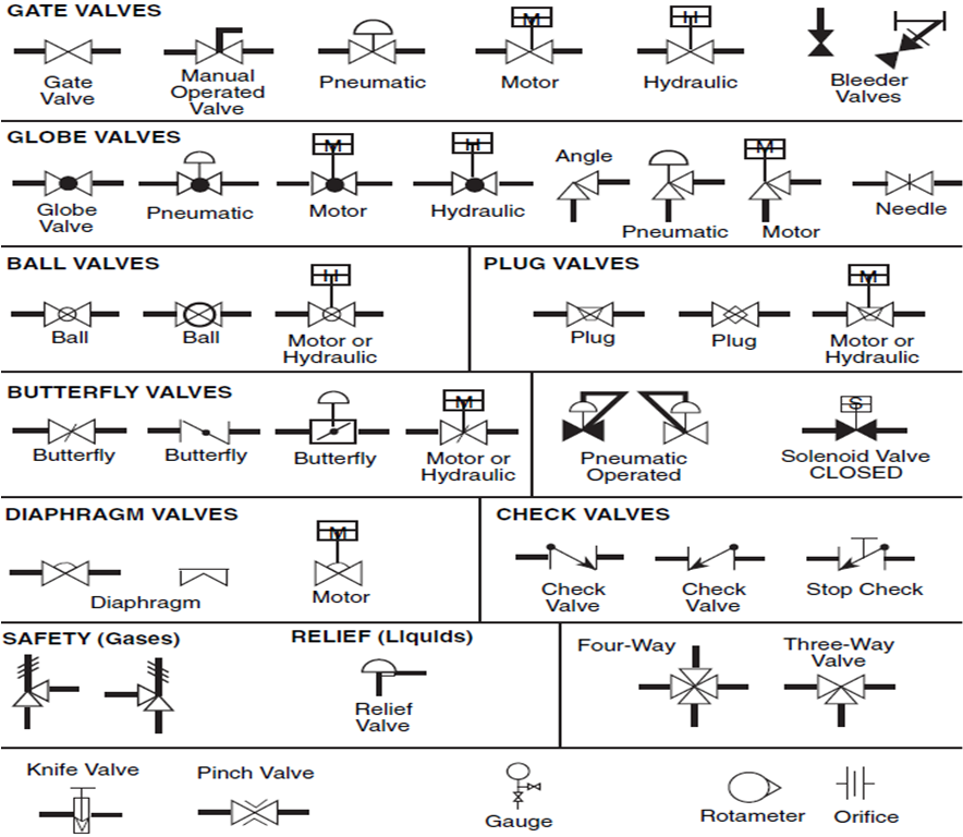
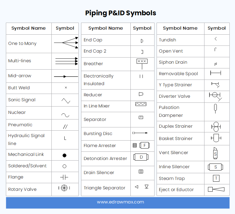
Web here’s an overview of some common piping symbols used in p&ids: Checkout list of such symbols given below. Web piping and instrumentation diagrams (p&ids) use specific symbols to show the connectivity of equipment, sensors, and valves in a control system. Edrawmax specializes in diagramming and visualizing. Pressure, temperature, flow, level, switches, alarms, and miscellaneous.

How to read isometric drawing piping dadver
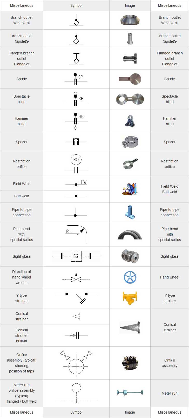
Web piping and instrumentation diagrams (p&ids) use specific symbols to show the connectivity of equipment, sensors, and valves in a control system. Web various symbols are used to indicate piping components, instrumentation, equipments in engineering drawings such as piping and instrumentation diagram (p&id), isometric drawings, plot plan, equipment layout, welding drawings etc. Web what are p&id symbols? The most popular.

What is Piping Isometric drawing? How to Read Piping Drawing? ALL
Switch to mac > try it free. Web a p&id or process and instrumentation diagram provides a detailed graphical representation of the actual process system that includes the piping, equipment, valves, instrumentation, and other process components in the system. With lucidchart, it's easy to access all of the featured p&id symbols. This single line is the centerline of the pipe,.
What is a P&ID Beginner’s Guide EdrawMax Online
A pipe into a isometric view, is always drawn by a single line. These symbols are categorized under the following headings: All components are represented using various p&id symbols. Pressure, temperature, flow, level, switches, alarms, and miscellaneous. Symbols for pumps, heat exchanger, pressure vessel, valves,and instruments etc.

standard piping symbols Engineering Feed
P and id symbols are used in engineering system designs to represent process working and sequence. 5 provides symbols for fans, pumps, and turbines. The most popular symbols are actuators, equipment, flow elements, instrumentation, piping fittings, valves and more. With lucidchart, it's easy to access all of the featured p&id symbols. Users can also import svg and other image files.

Basic Piping Isometric Symbols Piping Analysis YouTube
Pressure, temperature, flow, level, switches, alarms, and miscellaneous. Web symbols shown on fig. Web we've broken them down into seven main groups: A pipe into a isometric view, is always drawn by a single line. Learn from this article to know everything about plumbing symbols, and how to use or create plumbing symbols.
Piping Coordination System Mechanical symbols for Isometric drawings
P and id symbols are used in engineering system designs to represent process working and sequence. Users can also import svg and other image files to create a custom p&id library for any situation. Web a p&id or process and instrumentation diagram provides a detailed graphical representation of the actual process system that includes the piping, equipment, valves, instrumentation, and.

Piping Isometric Drawings The Piping Engineering World
Pressure, temperature, flow, level, switches, alarms, and miscellaneous. Web p&id and pfd drawing symbols and legend list. Equipment, piping, vessels, heat exchangers, pumps, instruments, and valves. These symbols are categorized under the following headings: All components are represented using various p&id symbols.
Piping and Instrumentation Diagram Software
A pipe into a isometric view, is always drawn by a single line. 5 provides symbols for fans, pumps, and turbines. P and id symbols are used in engineering system designs to represent process working and sequence. Web here’s an overview of some common piping symbols used in p&ids: How to read a piping isometric?
Web Edrawmax Includes More Than 2000 Vector P&Id Symbols Used To Depict Mechanical Equipment, Piping, Piping Components, Valves, Equipment Drivers, Instrumentations, And Controls.
Web here’s an overview of some common piping symbols used in p&ids: These symbols can represent actuators, sensors, and controllers and may be. This single line is the centerline of the pipe, and from that line, the dimensions measured. All components are represented using various p&id symbols.
Web Symbols Are Shown In Black Lines.
These symbols are categorized under the following headings: These symbols are categorized under the following headings: The most popular symbols are actuators, equipment, flow elements, instrumentation, piping fittings, valves and more. These symbols are categorized under the following headings:
How To Read A Piping Isometric?
These tools generate the 3d representation of the piping layout, including pipe dimensions, fittings,. Learn from this article to know everything about plumbing symbols, and how to use or create plumbing symbols. 5 provides symbols for fans, pumps, and turbines. Web piping and instrumentation diagrams (p&ids) use specific symbols to show the connectivity of equipment, sensors, and valves in a control system.
Lighter Lines Show Connected Pipe, And Are Not Parts Of The Symbols.
A pipe into a isometric view, is always drawn by a single line. P and id symbols are used in engineering system designs to represent process working and sequence. Pressure, temperature, flow, level, switches, alarms, and miscellaneous. It also has a standard method of indication for pipe fittings, valves piping & allied items on their plans.