Piping Drawing
Piping Drawing - Available for windows, mac and linux. Web pipe culverts and endwalls. We are concluding our first pipefitter series run with a video on how to draw isometric drawings. Web piping drawings are basically the schematic representations that define functional relationships in a piping or pipeline system. These drawings are impelled to supply a more detailed and authentic representation, emphasising the pipes, valves and other components’ shape, size and. The drawings would help to speed up the fabrication and erection work at the site. It’s most commonly used in the engineering field. It lists the various facility types where pipe drafting and design is applied and the types of companies that employ pipe drafters. Modern alternative to pencil and paper. Protected endwalls for round & oval pipes (pipe sizes 18” to 72”, all skews, 2:1 & 3:1 slopes) for endwall dimension.
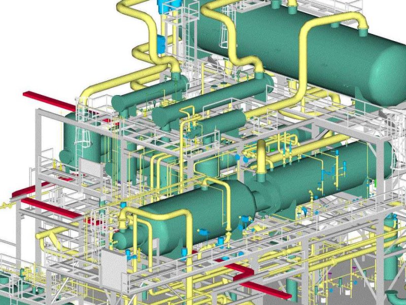
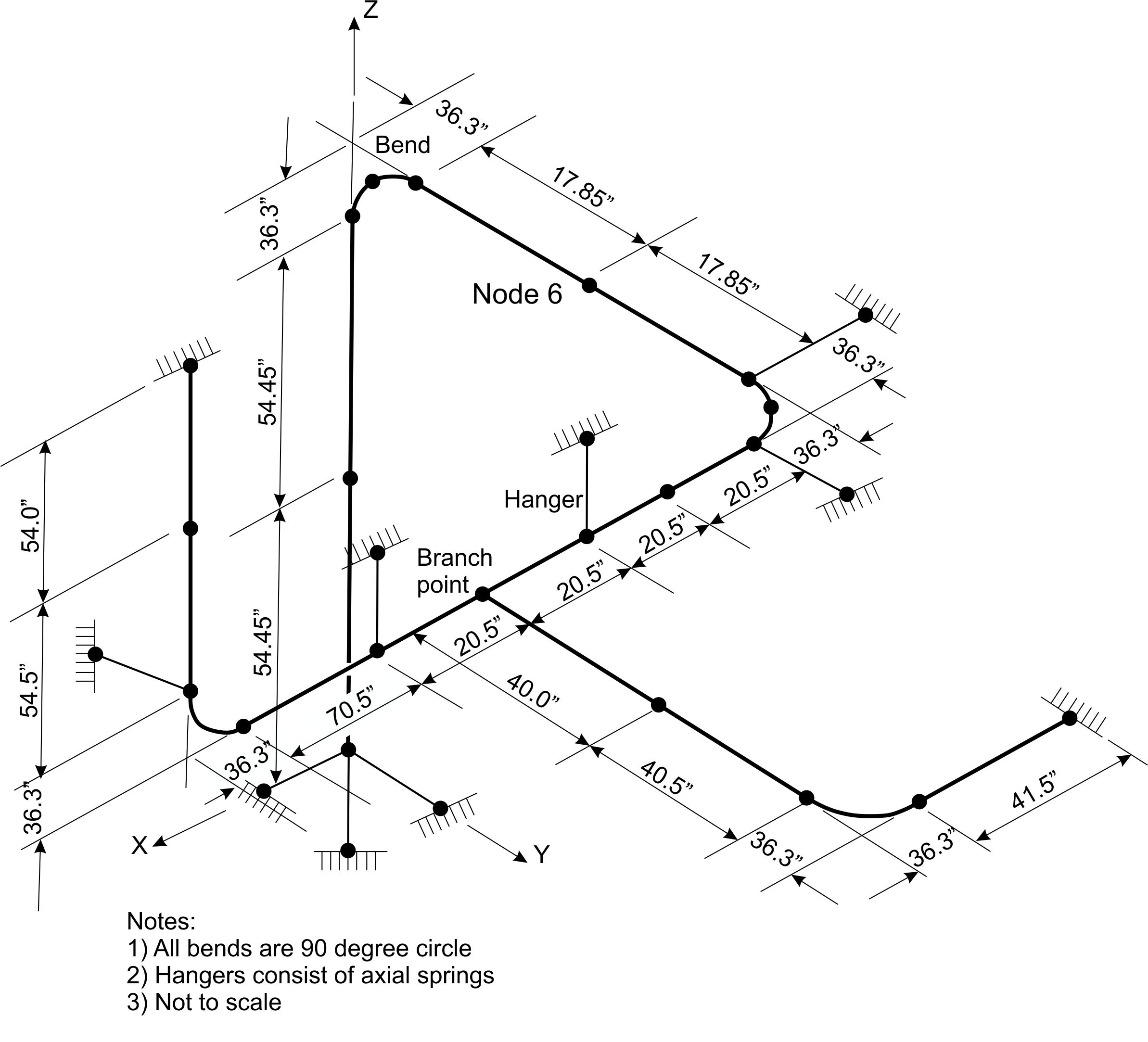
It’s most commonly used in the engineering field. Main graphic section consist of isometric representation of a pipe line route in 3d space, which includes following information : Web piping isometric is a representation of a single pipe line in a process plant with exact dimensions and bill of material (bom). Web in this article, we will explore all those piping drawings that are required to execute piping work. Web piping isometric drawing consists of three sections. Simplified chinese [auto] what you'll learn. Get tired of hand sketches and look for something better to use? The easiest way to visualize your piping process and instrumentation by using our professional piping design software. Fabrication, construction, and architectural drawings. In the world of industrial projects, precision and accuracy are of utmost importance.
The drawing axes of the isometrics intersect at an angle of 60°. Cad software with piping tools preinstalled. Web in this article, we will explore all those piping drawings that are required to execute piping work. Get tired of hand sketches and look for something better to use? It’s most commonly used in the engineering field. This information is displayed in the areas surrounding the graphic portion of the drawing. It is the most important deliverable of any project where piping plays a vital role. A through knowledge of the information presented in the title block, the revision block, the notes and legend, and the drawing grid is necessary before a drawing can be read. Start doing things in edrawmax online. A piping and instrumentation diagram, or p&id, shows the piping and related components of a physical process flow.

Piping Design Basics Piping Isometric Drawings Piping Isometrics
It lists the various facility types where pipe drafting and design is applied and the types of companies that employ pipe drafters. There are usually five types of piping drawings that are prepared to communicate various information in a simple and easy way. Main graphic section consist of isometric representation of a pipe line route in 3d space, which includes.

How to read piping isometric drawing, Pipe fitter training, Watch the
These drawings are impelled to supply a more detailed and authentic representation, emphasising the pipes, valves and other components’ shape, size and. Learn to read a piping isometric drawing and learn how to fabricate a pipe spool. The instructor explains the state of art in mechanical & piping drafting. Pipe segments can be displayed using single line or double line.
Piping Drawing at GetDrawings Free download
The drawings would help to speed up the fabrication and erection work at the site. The instructor explains the state of art in mechanical & piping drafting. 12k views 1 year ago tutorials for pipe fitters and fabricators. Process flow diagram (pfd) piping and instrumentation drawing (p&id). This information is displayed in the areas surrounding the graphic portion of the.

How to read isometric drawing piping dadver
Web a piping single line drawing (or piping one line drawing) is a piping drawing that shows the size and location of pipes, fittings and valves. Get tired of hand sketches and look for something better to use? Start doing things in edrawmax online. Download our valuable sizing tables and dimensioning charts, essential to properly design your piping system. A.
Piping Drawing at GetDrawings Free download
Web © 2024 google llc. Protected endwalls for round & oval pipes (pipe sizes 18” to 72”, all skews, 2:1 & 3:1 slopes) for endwall dimension. Web the drawing number, is also mandated in order for the client to be able to accept the drawing files back into the document management system and be able to retrieve them when required..
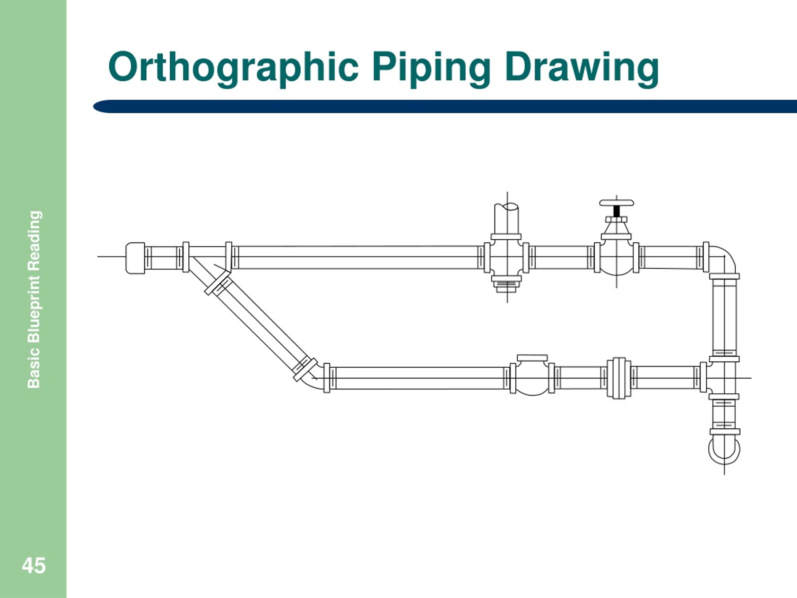
Piping orthographic drawing symbols kloology
These drawings are impelled to supply a more detailed and authentic representation, emphasising the pipes, valves and other components’ shape, size and. General arrangement drawing (gad)/piping plan drawing. Process flow diagram (pfd) piping and instrumentation drawing (p&id). The drawings would help to speed up the fabrication and erection work at the site. The easiest way to visualize your piping process.

How to read piping Isometric drawing YouTube
Web the main purpose of a piping drawing is to communicate the information in a simple way. Get tired of hand sketches and look for something better to use? This chapter is an overview of the pipe drafting and design profession. Download our valuable sizing tables and dimensioning charts, essential to properly design your piping system. These drawings are impelled.

Piping drawing and symbols
The drawings would help to speed up the fabrication and erection work at the site. Web piping and instrument drawings (p&ids), electrical single lines and schematics, electronic diagrams and schematics, logic diagrams and prints, and. Web it's quick, easy, and completely free. Start doing things in edrawmax online. Web piping isometric drawing software is an essential tool for piping engineers.

Piping Drawing at GetDrawings Free download
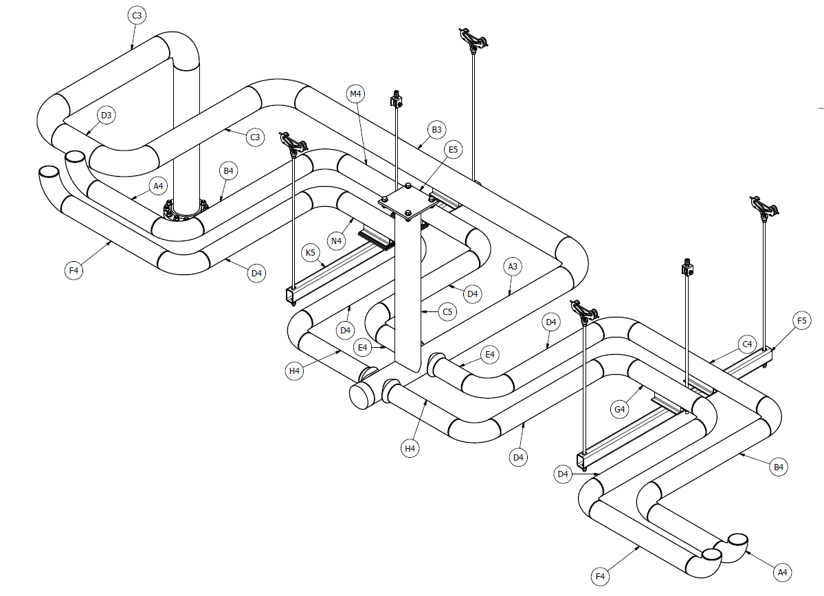
Any desired piping design views can be displayed on the drawing. Pipe segments can be displayed using single line or double line representation. Web pipe culverts and endwalls. Simplified chinese [auto] what you'll learn. Web a piping isometric drawing is a technical drawing that depicts a pipe spool or a complete pipeline using an isometric representation.
Piping Drawing at GetDrawings Free download
Main graphic section consist of isometric representation of a pipe line route in 3d space, which includes following information : It is drawn to scale so the relationships of the aforementioned are correctly shown. Get tired of hand sketches and look for something better to use? Web piping isometric drawing software is an essential tool for piping engineers and designers.
The Drawing Axes Of The Isometrics Intersect At An Angle Of 60°.
The easiest way to visualize your piping process and instrumentation by using our professional piping design software. Web piping and instrument drawings (p&ids), electrical single lines and schematics, electronic diagrams and schematics, logic diagrams and prints, and. It is the most important deliverable of any project where piping plays a vital role. Web a piping isometric drawing is a technical drawing that depicts a pipe spool or a complete pipeline using an isometric representation.
General Arrangement Drawing (Gad)/Piping Plan Drawing.
We are concluding our first pipefitter series run with a video on how to draw isometric drawings. Web the drawing number, is also mandated in order for the client to be able to accept the drawing files back into the document management system and be able to retrieve them when required. Web get your certificate here: These tools generate the 3d representation of the piping layout, including pipe dimensions, fittings, valves, and.
Web © 2024 Google Llc.
These drawings are impelled to supply a more detailed and authentic representation, emphasising the pipes, valves and other components’ shape, size and. A piping and instrumentation diagram, or p&id, shows the piping and related components of a physical process flow. It is the basic training document to explain the process details to operation guys, field engineers, and maintenance professionals. Main graphic section consist of isometric representation of a pipe line route in 3d space, which includes following information :
Web Piping Isometric Drawing Consists Of Three Sections.
Web in this article, we will explore all those piping drawings that are required to execute piping work. Download our valuable sizing tables and dimensioning charts, essential to properly design your piping system. This chapter is an overview of the pipe drafting and design profession. How to read iso drawings.