Pnid Drawings
Pnid Drawings - Web p&ids are used to develop guidelines and standards for facility operation. Web the p&id drawing is usually used in the process industry and engineering field. It is the basic training document to explain the process details to operation guys, field engineers, and maintenance professionals. The piping and instrumentation diagram is also known as the process engineering flow scheme, pefs. In this video, you will learn the basics of piping and instrumentation diagrams (also called p&id. P&id is more complex than pfd and includes lots of details. P&id software built with engineers in mind. It’s most commonly used in the engineering field. Web a piping and instrumentation diagram (p&id) is defined as follows: Web to draw a piping and instrumentation diagram, you’ll need a basic understanding of what a p&id is.
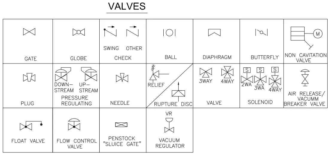
You may want to review a p&id symbols legend to ensure that you’re using the correct shapes in an appropriate context. 44k views 2 years ago instrumentation tools. It uses symbols to represent process equipment such as sensors and controllers. You will learn how to read p&id and pefs with the help of the actual plant drawing. A piping and instrumentation diagram, or p&id, shows the piping and related components of a physical process flow. Web want to draw piping and instrumentation diagrams? P&id software built with engineers in mind. Web a piping and instrumentation diagram (p&id) is defined as follows: Web to draw a piping and instrumentation diagram, you’ll need a basic understanding of what a p&id is. It is the basic training document to explain the process details to operation guys, field engineers, and maintenance professionals.
Web here, i have tried to explain p&id and pefs in an easy way. Piping and instrumentation diagrams are useful instruments when it comes to the design, modification, and maintenance of an engineering process. Web want to draw piping and instrumentation diagrams? Web p&id drawing is a schematic representation of instrumentations, control systems, and pipelines used in any process development plant. Web to draw a piping and instrumentation diagram, you’ll need a basic understanding of what a p&id is. In this video, you will learn the basics of piping and instrumentation diagrams (also called p&id. Our streamlined p&id software makes it easy for piping designers and electrical, mechanical, and process engineers to create accurate depictions of piping structures and other related components. 44k views 2 years ago instrumentation tools. It is the basic training document to explain the process details to operation guys, field engineers, and maintenance professionals. In the process industry, a standard set of symbols is.
Piping and Instrumentation Diagram Tool
The piping and instrumentation diagram is also known as the process engineering flow scheme, pefs. Web want to draw piping and instrumentation diagrams? The p&id drawings help them to track the interconnection between the piping and instrumentation and equipment. Web a piping and instrumentation diagram (p&id) is defined as follows: P&id is more complex than pfd and includes lots of.
How to Read a P&ID Drawing Quickly and Easily Edraw Max
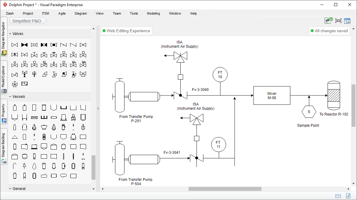
Visual paradigm's p&id tool features a handy diagram editor that allows you to draw p&id diagrams, industrial diagrams, and schematics quickly and easily. It is the basic training document to explain the process details to operation guys, field engineers, and maintenance professionals. Web a piping and instrumentation diagram (p&id) is defined as follows: You will learn how to read p&id.
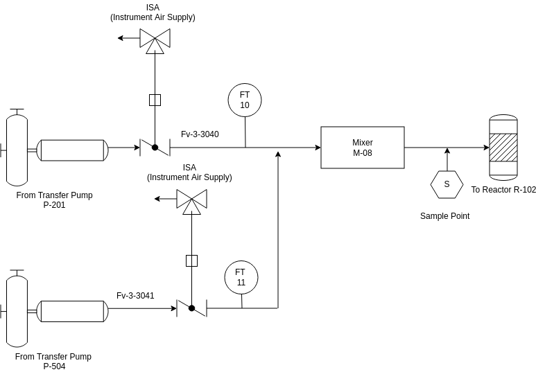
Simplified P&ID Piping and Instrumentation Diagram Template
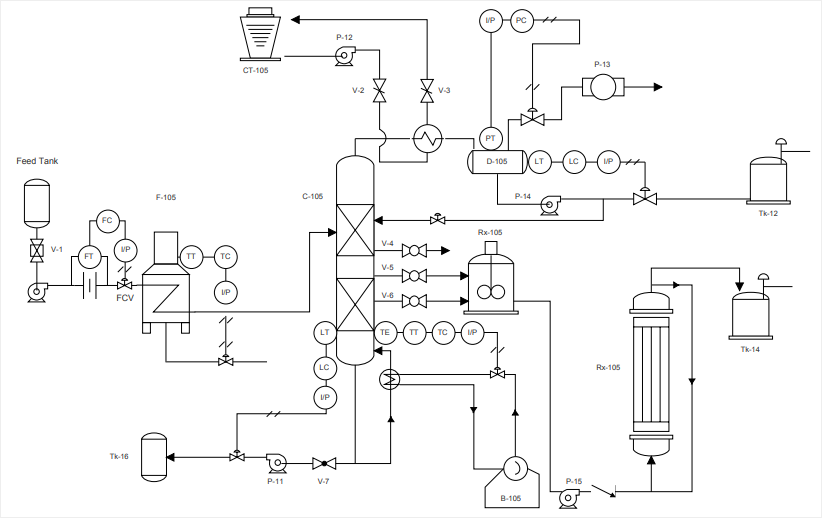
It uses symbols to represent process equipment such as sensors and controllers. P&id is more complex than pfd and includes lots of details. The p&id drawings help them to track the interconnection between the piping and instrumentation and equipment. A piping and instrumentation diagram, or p&id, shows the piping and related components of a physical process flow. Web p&id drawing.
What is a P&ID Drawing P&ID Symbols How to Read P & ID Drawings
Web it's quick, easy, and completely free. Every symbol contains letters and a number. The piping and instrumentation diagram is also known as the process engineering flow scheme, pefs. You may want to review a p&id symbols legend to ensure that you’re using the correct shapes in an appropriate context. In the process industry, a standard set of symbols is.
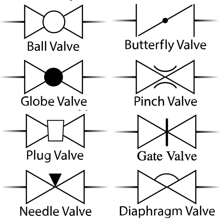
P&IDs (Piping & Instrumentation Diagrams) and P&ID Valve Symbol Library
A diagram which shows the interconnection of process equipment and the instrumentation used to control the process. 44k views 2 years ago instrumentation tools. Web a piping and instrumentation diagram (p&id) is defined as follows: P&id is more complex than pfd and includes lots of details. In the process industry, a standard set of symbols is.

Learn How to Read P&ID Drawings A Complete Guide
In the process industry, a standard set of symbols is. Web here, i have tried to explain p&id and pefs in an easy way. The piping and instrumentation diagram is also known as the process engineering flow scheme, pefs. Web a piping and instrumentation diagram (p&id) is defined as follows: It uses symbols to represent process equipment such as sensors.

Piping and Instrumentation Documents Instrumentation Tools
44k views 2 years ago instrumentation tools. Web want to draw piping and instrumentation diagrams? It is the basic training document to explain the process details to operation guys, field engineers, and maintenance professionals. Web p&ids are used to develop guidelines and standards for facility operation. Piping and instrumentation diagrams are useful instruments when it comes to the design, modification,.
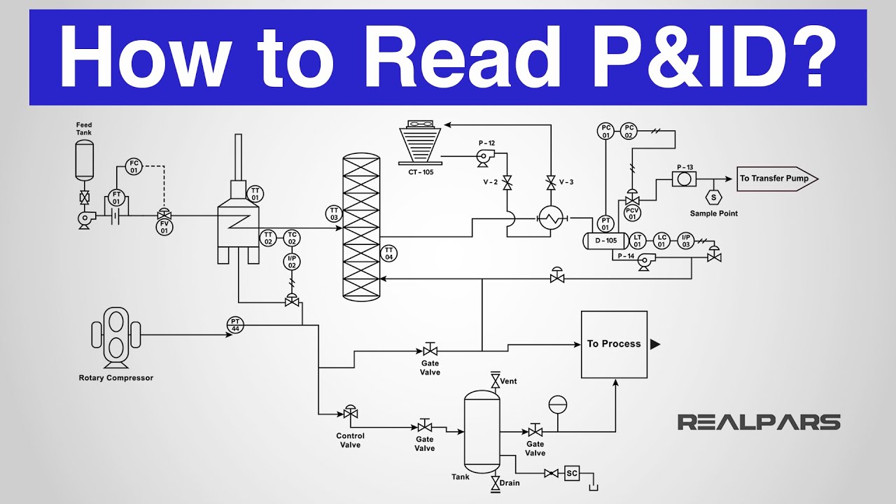
How to Read a P&ID? (Piping & Instrumentation Diagram) YouTube
Web p&ids are used to develop guidelines and standards for facility operation. Piping and instrumentation diagrams are useful instruments when it comes to the design, modification, and maintenance of an engineering process. A piping and instrumentation diagram, or p&id, shows the piping and related components of a physical process flow. Web a piping and instrumentation diagram (p&id) is defined as.

Learn How to Read P&ID Drawings A Complete Guide (2023)
Every symbol contains letters and a number. You will learn how to read p&id and pefs with the help of the actual plant drawing. Web a piping and instrumentation diagram (p&id) is defined as follows: Web want to draw piping and instrumentation diagrams? 44k views 2 years ago instrumentation tools.
GitHub ERhysT/pnid Piping and instrumentation diagram drawing canvas
Piping and instrumentation diagrams are useful instruments when it comes to the design, modification, and maintenance of an engineering process. You may want to review a p&id symbols legend to ensure that you’re using the correct shapes in an appropriate context. Visual paradigm's p&id tool features a handy diagram editor that allows you to draw p&id diagrams, industrial diagrams, and.
Web P&Ids Are Used To Develop Guidelines And Standards For Facility Operation.
Web a piping and instrumentation diagram (p&id) is defined as follows: The piping and instrumentation diagram is also known as the process engineering flow scheme, pefs. You may want to review a p&id symbols legend to ensure that you’re using the correct shapes in an appropriate context. Web p&id drawing is a schematic representation of instrumentations, control systems, and pipelines used in any process development plant.
You Will Learn How To Read P&Id And Pefs With The Help Of The Actual Plant Drawing.
Web here, i have tried to explain p&id and pefs in an easy way. In the process industry, a standard set of symbols is. It uses symbols to represent process equipment such as sensors and controllers. The p&id drawings help them to track the interconnection between the piping and instrumentation and equipment.
It Is The Basic Training Document To Explain The Process Details To Operation Guys, Field Engineers, And Maintenance Professionals.
Piping and instrumentation diagrams are useful instruments when it comes to the design, modification, and maintenance of an engineering process. It’s most commonly used in the engineering field. Web the p&id drawing is usually used in the process industry and engineering field. Every symbol contains letters and a number.
P&Id Is More Complex Than Pfd And Includes Lots Of Details.
P&id software built with engineers in mind. Visualize and understand your piping structures and processes. A diagram which shows the interconnection of process equipment and the instrumentation used to control the process. Visual paradigm's p&id tool features a handy diagram editor that allows you to draw p&id diagrams, industrial diagrams, and schematics quickly and easily.