Printable Smith Chart
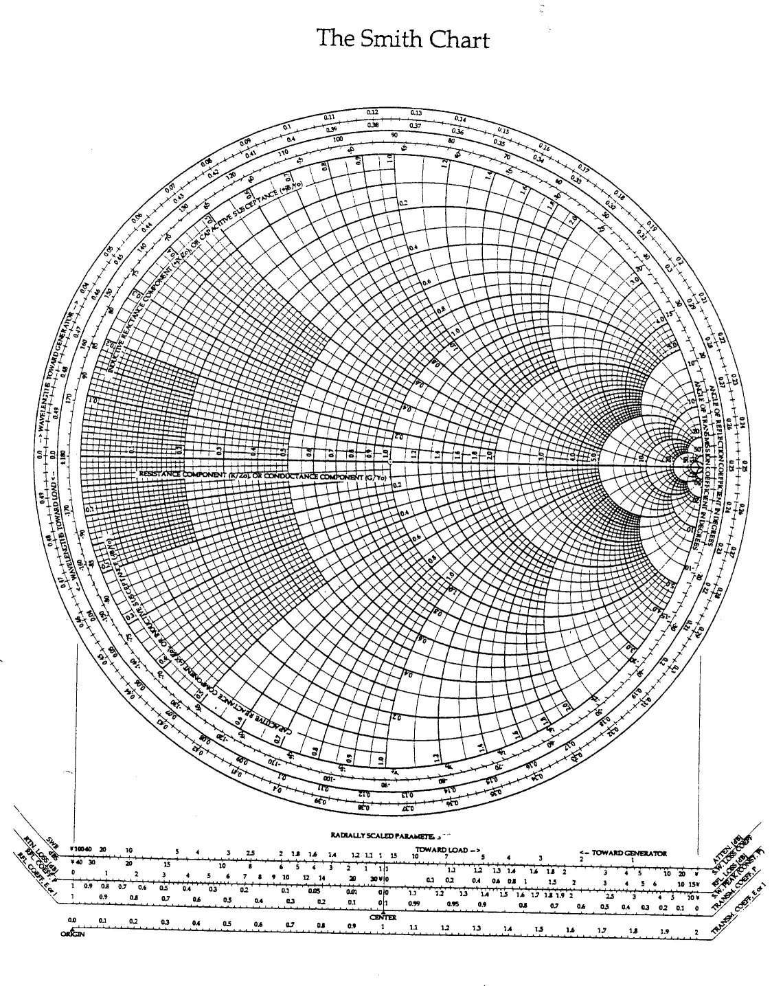
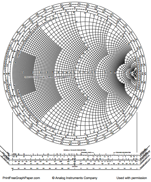
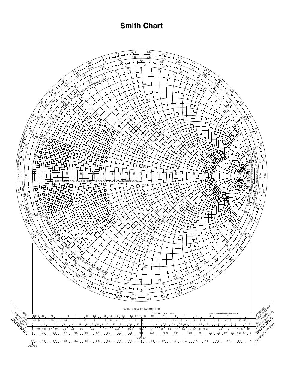
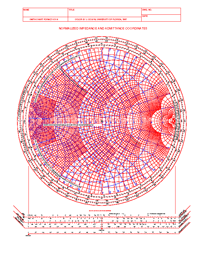
Printable Smith Chart - Web 0.1 0.1 0.1 0.2 0.2 0.2 0.3 0.3 0.3 0.4 0.4 0.4 0.5 0.5 0.5 0.6 0.6 0.6 0.7 0.7 0.7 0.8 0.8 0.8 0.9 0.9 0.9 1.0 1.0 1.0 1.2 1.2 1.2 1.4 1.4 1.4 1.6 1.6 1.6 1.8 1.8 1. Of eecs the smith chart say we wish to map a line on the normalized complex impedance plane onto the complex γ plane. Transmission coefficient, which equals unity plus reflection coefficient, may also be plotted (see below). 2) a visual indication of microwave device performance. Æ it exists on the complex γ plane. A network analyzer (hp 8720a) showing a smith chart. Web the complete smith chart 10 resistan e component r or condu black magic design 012 ance component( radially scaled parameters toward generator Matching ladder networks with capacitors, inductors, resistors, serie and parallel rlc, transformers, serie lines and open or shorted stubs. Web radio frequency engineering tools. Web smith charts lecture outline •construction of the smith chart •admittance and impedance •circuit theory •determining vswr and •impedance transformation •impedance matching slide 2 1 2
Web from here you can click the links to enter the smith chart tutorial pages, and learn about impedance matching for antennas. The smith chart is used by electrical and electronics engineers to aid in demonstrating and solving problems in radio frequency engineering. Web as one of the most important microwave engineering tools, smith chart has been widely used by microwave engineers worldwide. Ü÷ ÿmã |üó ý÷óçÿøwÿ]ü÷yù ×óùóø¼|üññx>¯÷ëçåqý> ‡ûíóvæñêãóô1 ëåóññûž r=>§ïùæ#¨ öù|ã×ûá· çãót»€ìôy9_evû|^n ; Those with negative real parts map outside the circle. Web 0.1 0.1 0.1 0.2 0.2 0.2 0.3 0.3 0.3 0.4 0.4 0.4 0.5 0.5 0.5 0.6 0.6 0.6 0.7 0.7 0.7 0.8 0.8 0.8 0.9 0.9 0.9 1.0 1.0 1.0 1.2 1.2 1.2 1.4 1.4 1.4 1.6 1.6 1.6 1.8 1.8 1. Web the smith chart is a graphical calculator or nomogram that was invented by phillip hagar smith at bell laboratories in 19391 to quickly calculate important transmission line parameters such as reflection coefficients or input impedances. 1) a graphical method to solve many transmission line problems. A network analyzer (hp 8720a) showing a smith chart. Web what is a smith chart?
Fill, sign and download smith chart online on handypdf.com. Web what is a smith chart? Web 0.1 0.1 0.1 0.2 0.2 0.2 0.3 0.3 0.3 0.4 0.4 0.4 0.5 0.5 0.5 0.6 0.6 0.6 0.7 0.7 0.7 0.8 0.8 0.8 0.9 0.9 0.9 1.0 1.0 1.0 1.2 1.2 1.2 1.4 1.4 1.4 1.6 1.6 1.6 1.8 1.8 1. Circles and contours for stability, noise figure, gain, vswr and q. This article covers the mathematics behind creating the chart and its physical interpretation. Free settable normalisation impedance for the smith chart. Web smith charts lecture outline •construction of the smith chart •admittance and impedance •circuit theory •determining vswr and •impedance transformation •impedance matching slide 2 1 2 Matching ladder networks with capacitors, inductors, resistors, serie and parallel rlc, transformers, serie lines and open or shorted stubs. Web smith charts are an extremely useful tool for engineers and designers concerned with rf circuits. The smith chart is essentially a polar plot of the complex reflection coefficient, |γ|, as a function of electrical length along the transmission line.
Smith Charts
1) a graphical method to solve many transmission line problems. The smith chart is essentially a polar plot of the complex reflection coefficient, |γ|, as a function of electrical length along the transmission line. Of eecs the smith chart say we wish to map a line on the normalized complex impedance plane onto the complex γ plane. Web learn how.
Printable Graphing Paper for Free
Free settable normalisation impedance for the smith chart. Web as one of the most important microwave engineering tools, smith chart has been widely used by microwave engineers worldwide. Complex numbers with positive real parts map inside the circle. Web radio frequency engineering tools. Transmission coefficient, which equals unity plus reflection coefficient, may also be plotted (see below).

Smith Chart 5 Free Templates in PDF, Word, Excel Download
Ü÷ ÿmã |üó ý÷óçÿøwÿ]ü÷yù ×óùóø¼|üññx>¯÷ëçåqý> ‡ûíóvæñêãóô1 ëåóññûž r=>§ïùæ#¨ öù|ã×ûá· çãót»€ìôy9_evû|^n ; Web fillable and printable smith chart 2024. The most important fact about the smith chart is: Web learn how a series rlc circuit with arbitrary component values can be represented as a point on the smith chart and how an impedance contour on the smith chart can be used.

Printable Smith Chart Printable Templates
Free settable normalisation impedance for the smith chart. Fill, sign and download smith chart online on handypdf.com. Ü÷ ÿmã |üó ý÷óçÿøwÿ]ü÷yù ×óùóø¼|üññx>¯÷ëçåqý> ‡ûíóvæñêãóô1 ëåóññûž r=>§ïùæ#¨ öù|ã×ûá· çãót»€ìôy9_evû|^n ; Web from here you can click the links to enter the smith chart tutorial pages, and learn about impedance matching for antennas. 1) a graphical method to solve many transmission line problems.

Printable Smith Chart
The smith chart is used by electrical and electronics engineers to aid in demonstrating and solving problems in radio frequency engineering. Fill, sign and download smith chart online on handypdf.com. Determining vswr, rl, and much more. Web the smith chart is a graphical calculator or nomogram that was invented by phillip hagar smith at bell laboratories in 19391 to quickly.

The Smith Chart A Vital Graphical Tool DigiKey
Web 2/17/2010 the smith chart 1/10 jim stiles the univ. A network analyzer (hp 8720a) showing a smith chart. Web by plotting the normalized load impedance on a smith chart, the input impedance as a function of line length can be found. Web smith charts lecture outline •construction of the smith chart •admittance and impedance •circuit theory •determining vswr and.

Printable Smith Chart
This article covers the mathematics behind creating the chart and its physical interpretation. Web a smith chart is a graphical tool used by engineers to help design, match, and troubleshoot electrical transmission lines. Web the smith chart was invented by phillip smith in 1939 in order to provide an easily usable graphical representation of the complex reflection coefficient γ and.

Complete Smith Chart Template Free Download
The most important fact about the smith chart is: The smith chart also provides the value of the reflection Web from here you can click the links to enter the smith chart tutorial pages, and learn about impedance matching for antennas. Web smith charts are an extremely useful tool for engineers and designers concerned with rf circuits. Matching ladder networks.
Black and White Smith Chart Download Printable PDF Templateroller
Fill, sign and download smith chart online on handypdf.com. The smith chart also provides the value of the reflection Web by plotting the normalized load impedance on a smith chart, the input impedance as a function of line length can be found. Web smith charts lecture outline •construction of the smith chart •admittance and impedance •circuit theory •determining vswr and.
A Collection of Smith Chart Resources
A network analyzer (hp 8720a) showing a smith chart. Web what is a smith chart? The smith chart also provides the value of the reflection Web by plotting the normalized load impedance on a smith chart, the input impedance as a function of line length can be found. Web 2/17/2010 the smith chart 1/10 jim stiles the univ.
Determining Vswr, Rl, And Much More.
Web the smith chart is a graphical calculator or nomogram that was invented by phillip hagar smith at bell laboratories in 19391 to quickly calculate important transmission line parameters such as reflection coefficients or input impedances. 2) a visual indication of microwave device performance. Download for free (pdf format) Web smith charts lecture outline •construction of the smith chart •admittance and impedance •circuit theory •determining vswr and •impedance transformation •impedance matching slide 2 1 2
Ü÷ Ÿmã |Üó Ý÷Óçÿøwÿ]Ü÷Yù ×Óùóø¼|Üññx>¯÷Ëçåqý> ‡Ûíóvæñêãóô1 Ëåóññûž R=>§Ïùæ#¨ Öù|Ã×Ûá· Çãót»€Ìôy9_Evû|^N ;
A network analyzer (hp 8720a) showing a smith chart. Web learn how a series rlc circuit with arbitrary component values can be represented as a point on the smith chart and how an impedance contour on the smith chart can be used to describe the circuit's frequency response. Web 2/17/2010 the smith chart 1/10 jim stiles the univ. Matching ladder networks with capacitors, inductors, resistors, serie and parallel rlc, transformers, serie lines and open or shorted stubs.
Transmission Coefficient, Which Equals Unity Plus Reflection Coefficient, May Also Be Plotted (See Below).
The smith chart is used by electrical and electronics engineers to aid in demonstrating and solving problems in radio frequency engineering. Web as one of the most important microwave engineering tools, smith chart has been widely used by microwave engineers worldwide. Of eecs the smith chart say we wish to map a line on the normalized complex impedance plane onto the complex γ plane. The smith chart also provides the value of the reflection
Web What Is A Smith Chart?
Web the smith chart was invented by phillip smith in 1939 in order to provide an easily usable graphical representation of the complex reflection coefficient γ and reading of the associated complex terminating impedance γ is defined as the ratio of electrical field strength of the reflected versus forward travelling wave The most important fact about the smith chart is: Edit element values after insertion. Web the complete smith chart 10 resistan e component r or condu black magic design 012 ance component( radially scaled parameters toward generator