Ref Dimension On Drawing
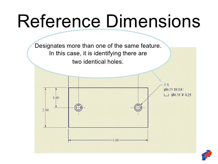
Ref Dimension On Drawing - Web to add a reference dimension: A reference dimension is a repeat of a dimension or is derived from other values on the drawing or related drawings. Basic requirements for dimensioning in part drawings. Web reference dimensions are shown on a drawing as a value enclosed in parentheses. Point to the silhouette edge, and when the pointer appears, click to dimension. In many instances, they make a representation better to understand. Dimension preview in creo cad software. To create a new reference dimension. Web the new ipad pro — the thinnest apple product ever — features a stunningly thin and light design, taking portability to a whole new level. Reference dimensions are provided for a variety of reasons and are often an accumulation of other dimensions that are defined elsewhere [2] (e.g.
These are called out on. Dimension preview in creo cad software. The symbolic name for a reference dimension is rsd# ref, where # represents the dimension id. Jan 13, 2016 03:35 pm. To create a new reference dimension. An alternate method is to follow the dimension with “reference” or “ref”. 3.2k views 8 months ago technical drawing and gd&t. Web use the reference dimension tool to create a new reference dimension, or use the shortcut menu or the sketch menu to convert a normal dimension to a reference dimension. True, they are most commonly identified with parenthesis (1.250), but is there anything that controls this by way of actual standard? Click smart dimension (dimensions/relations toolbar) or click tools > dimensions > smart.
An alternate method is to follow the dimension with “reference” or “ref”. Basic dimensions are enclosed in a rectangular box & have no tolerance. It does not govern production or inspection operations. Methods and steps for dimensioning parts. Click the reference dimension icon to add parentheses around the dimension value and identify it as a reference dimension. In a drawing view, click the items you want to dimension. Click smart dimension (dimensions/relations toolbar) or click tools > dimensions > smart. Web reference dimensions are shown on a drawing as a value embedded with parentheses. Kevin_6462 july 6, 2021, 9:14am 1. Web to add a reference dimension:
Dimensioning standards
Click smart dimension (dimensions/relations toolbar) or click tools > dimensions > smart. Reference dimensions must have at least one section geometry entity. You can create new reference dimensions, and you can convert existing dimensions to reference dimensions. This means you can ensure your drawings are as clear and readable as possible. Kevin_6462 july 6, 2021, 9:14am 1.
Dimensioning In Engineering Drawing Ppt
Web to add a reference dimension: Do i have to add the parenthesis. Point to the silhouette edge, and when the pointer appears, click to dimension. Reference dimensions are provided for a variety of reasons and are often an accumulation of other dimensions that are defined elsewhere [2] (e.g. This allows machinists, for example, to quickly assess what stock material.
Dimensioning on technical drawing THEME 4 Introduction
The use of “ref” or enclose the dimension inward parentheses are. Web to add a reference dimension: In a drawing view, click the items you want to dimension. You can dimension to a silhouette edge. Below are some tips for working with dimensions.
Dimensioning on technical drawing THEME 4 Introduction
In a drawing view, click the items you want to dimension. Web reference dimensions are shown on a drawing as a value enclosed in parentheses. You can dimension to a silhouette edge. In autocad follow these steps: Web access the dimension dialog.
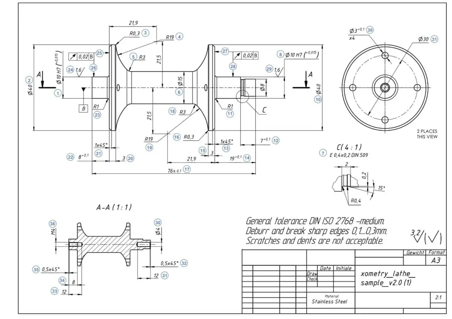
How To Prepare A Perfect Technical Drawing Xometry Europe
Web reference dimensions are shown on a drawing as a value enclosed in parentheses. An alternate method is to follow the dimension with “reference” or “ref”. Click the reference dimension icon to add parentheses around the dimension value and identify it as a reference dimension. Web engineering educator academy. You can dimension to a silhouette edge.
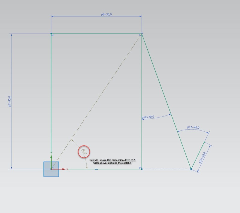
How can I use reference dimension to drive a sketch dimension in the
It does not govern production or inspection operations. You can create new reference dimensions, and you can convert existing dimensions to reference dimensions. One can pack a great deal of information into an isometric drawing. In a drawing view, click the items you want to dimension. Web a reference dimension is a dimension on an engineering drawing provided for information.

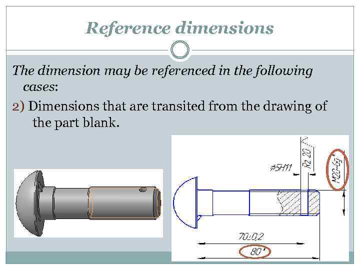
Correct Application of Reference Dimension? Drafting Standards, GD&T
An alternate method is until follow who dimension in “reference” or “ref”. Web reference measurement are shown upon a drawing as a value enclosed int parentheses. You can dimension to a silhouette edge. Basic dimensions are enclosed in a rectangular box & have no tolerance. Click power dimensioning > edit > edit dim text.
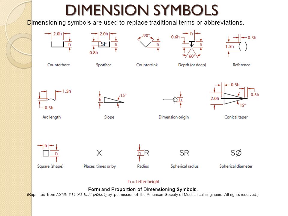
25+ Best Looking For Dimensioning Engineering Drawing Symbols And Their
Below are some tips for working with dimensions. Reference dimensions are provided for a variety of reasons and are often an accumulation of other dimensions that are defined elsewhere [2] (e.g. In a drawing view, click the items you want to dimension. Click sketch > reference and select the entities to define the dimension. 3.2k views 8 months ago technical.

Correct Application of Reference Dimension? Drafting Standards, GD&T
Web if the isometric drawing can show all details and all dimensions on one drawing, it is ideal. You can dimension to a silhouette edge. In a drawing view, click the items you want to dimension. Web one of the most common usages of reference dimensions on part drawings is to call out the total part size (bounding box) via.
Dimensioning on technical drawing THEME 4 Introduction
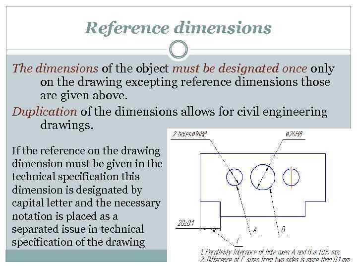
In a drawing view, click the items you want to dimension. Web a reference dimension is a dimension on an engineering drawing provided for information only. The dimensions in the part drawing shall be marked in accordance with the standard, complete, clear and reasonable. Kevin_6462 july 6, 2021, 9:14am 1. You can dimension to a silhouette edge.
You Can Dimension To A Silhouette Edge.
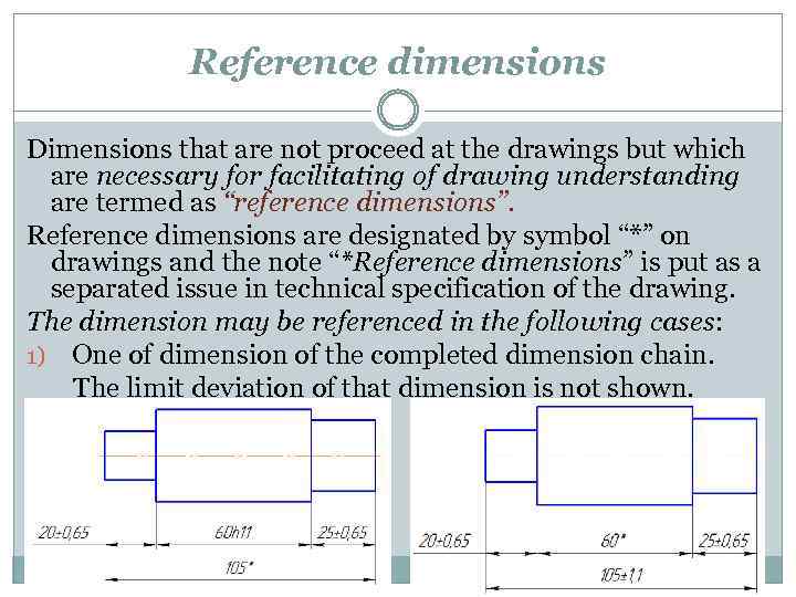
On the drawing or other related documentation). These notations are specified in asme y14.5 the dimensioning and. Web reference dimensions are shown on a drawing as a value embedded with parentheses. Web if the isometric drawing can show all details and all dimensions on one drawing, it is ideal.
Web A Reference Dimension Is A Dimension On An Engineering Drawing Provided For Information Only.
True, they are most commonly identified with parenthesis (1.250), but is there anything that controls this by way of actual standard? There is no gd&t symbol for a reference measuring. Click smart dimension (dimensions/relations toolbar) or click tools > dimensions > smart. In a drawing view, click the items you want to dimension.
It Does Not Govern Production Or Inspection Operations.
Basic dimensions are enclosed in a rectangular box & have no tolerance. The use of “ref” or enclose the dimension inward parentheses are. Point to the silhouette edge, and when the pointer appears, click to dimension. Dimension preview in creo cad software.
These Are Called Out On.
Web reference dimensions are shown on a drawing as a value enclosed in parentheses. Web access the dimension dialog. Web engineering educator academy. In autocad follow these steps: