Reference Dimensions On Drawings
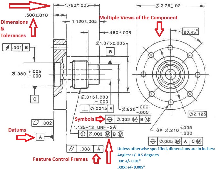
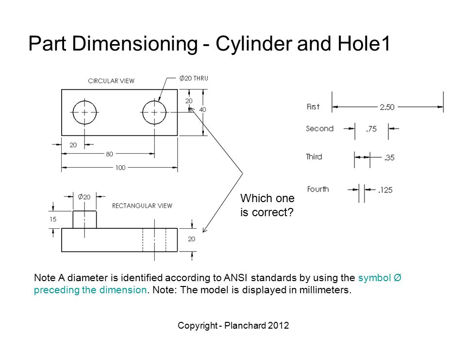
Reference Dimensions On Drawings - Dimensions shall be selected and arranged to suit the function and mating relationship of a part and shall not be subject to more than one interpretation. There is no gd&t symbol for a reference measuring. The employ of “ref” or enclosing the dimension inside parentheses what by from the of common notations former. Gd&t flatness is a common symbol that references how flat a surface is regardless of any other datum’s or features. In a drawing view, click the items you want to dimension. Click smart dimension (dimensions/relations toolbar) or click tools > dimensions > smart. An alternate method is to follow the dimension with “reference” or “ref”. Click smart dimension (dimensions/relations toolbar) or click tools, dimensions, smart. You can dimension to a silhouette edge. It comes in useful if a feature is to be defined on a drawing that needs to be uniformly flat without tightening any other dimensions on.
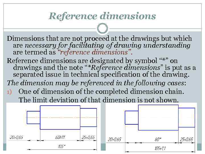
Web how are reference dimensions shown on a drawing? Dimensions shall be selected and arranged to suit the function and mating relationship of a part and shall not be subject to more than one interpretation. Point to the silhouette edge, and when the pointer appears, click to dimension. Many of the definitions are not official asme, ansi or iso terminology. Web to add a reference dimension: [1] reference dimensions are provided for a variety of reasons and are often an accumulation of other dimensions that are defined elsewhere [2] (e.g. A reference dimension is a repeat of a dimension or is derived from other values shown on the drawing or on related drawings. To learn the basics of gd&t, check out our gd&t 101 article which includes the definitions and utilization of: A reference dimension is a repeat of a dimension or is derived from other values on the drawing or related drawings. The purpose of engineering drawings.
It does not govern production or inspection operations. The purpose of engineering drawings. Phantom lines are used to represent a movable feature in its different positions. An alternate method is until follow who dimension in “reference” or “ref”. Click smart dimension (dimensions/relations toolbar) or click tools > dimensions > smart. In a drawing view, click the items you want to dimension. Point to the silhouette edge, and when the pointer appears, click to dimension. The drawing should define a part without specifying manufacturing methods. Web dimensioning of part drawings. Web a comprehensive reference database of dimensioned drawings documenting the standard measurements and sizes of the everyday objects and spaces that make up our world.
Dimensioning standards
Either way, the dimension does not get inspected. It does not govern production or inspection operations. Web as are reference dimensions shown on a drawing? [1] reference dimensions are provided for a variety of reasons and are often an accumulation of other dimensions that are defined elsewhere [2] (e.g. How are reference dimensions shown on a drawing?
Engineering Drawings & GD&T For the Quality Engineer
Section lines (hatching) are used in section views to represent surfaces of an object cut by a cutting plane. Click smart dimension (dimensions/relations toolbar) or click tools > dimensions > smart. (.250) gd&t reference & training books: Point to the silhouette edge, and when the pointer appears, click to dimension. These are called out on a drawing using parenthesis (i.e.,.
Dimensioning on technical drawing THEME 4 Introduction
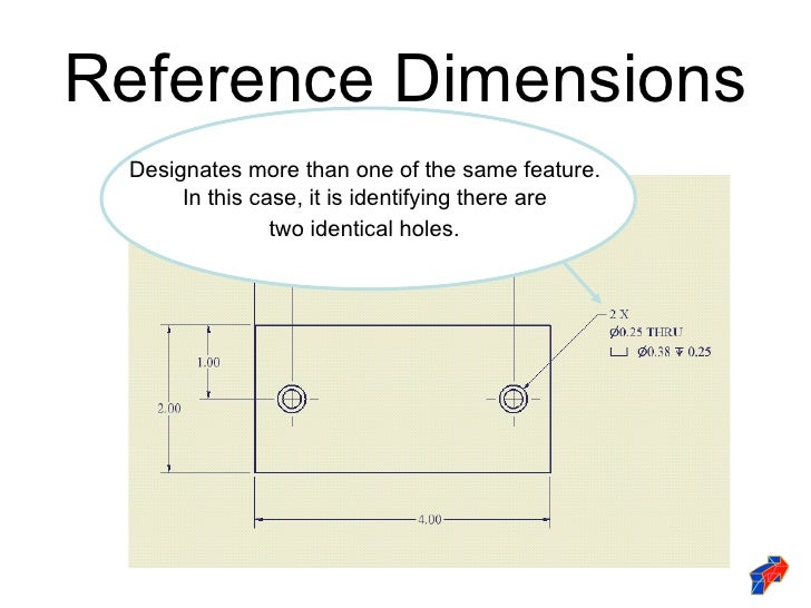
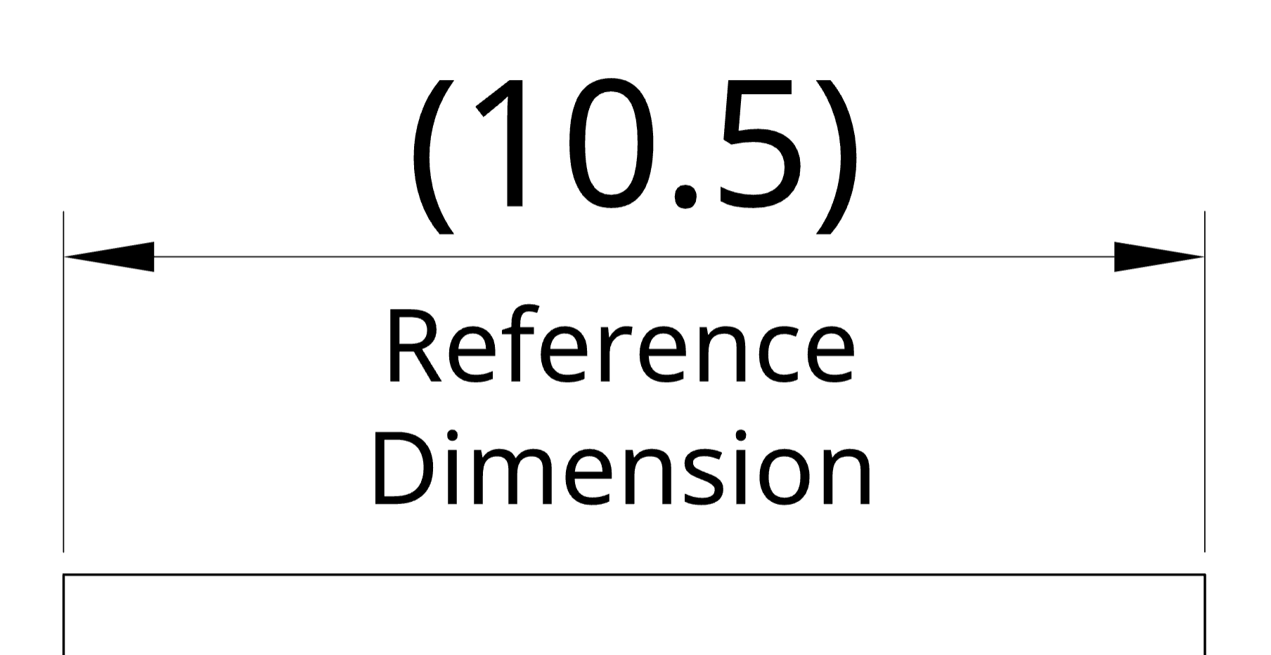
Reference dimensions are shown on a drawing as a value enclosed in parentheses. Web a reference dimension is a dimension on an engineering drawing provided for information only. Either way, the dimension does not get inspected. Many of the definitions are not official asme, ansi or iso terminology. Point to the silhouette edge, and when the pointer appears, click to.

DRAWING BASICS
Reference dimensions are shown on a drawing as a value enclosed in parentheses. Datums are theoretically exact points, axes, lines, and planes or a combination thereof that are derived from datum features. In a drawing view, click the items you want to dimension. When to use a reference dimension; Web to add a reference dimension:
Tolerances IT Grades, General Tolerances
How are reference dimensions shown on a drawing? It is considered auxiliary information and does not govern production or inspection operations. An alternate method is to follow the default with “reference” or “ref”. Do reference dimensions have tolerances? In a drawing view, click the items you want to dimension.
Drawing Dimension Symbols at Explore collection of
Click smart dimension (dimensions/relations toolbar) or click tools > dimensions > smart. Point to the silhouette edge, and when the pointer appears, click to dimension. Section lines (hatching) are used in section views to represent surfaces of an object cut by a cutting plane. There is no gd&t symbol for a reference dimension. Datums are theoretically exact points, axes, lines,.
Drafting And Dimensioning Symbols vrogue.co
An alternate method is until follow who dimension in “reference” or “ref”. Web a comprehensive reference database of dimensioned drawings documenting the standard measurements and sizes of the everyday objects and spaces that make up our world. In a drawing view, click the items you want to dimension. There is no gd&t symbol for a reference dimension. Click smart dimension.

Drawing Dimension Symbols at Explore collection of
Gd&t flatness is a common symbol that references how flat a surface is regardless of any other datum’s or features. [1] reference dimensions are provided for a variety of reasons and are often an accumulation of other dimensions that are defined elsewhere [2] (e.g. Web reference dimensions are shown on a drawing as a value enclosed in parentheses. The use.
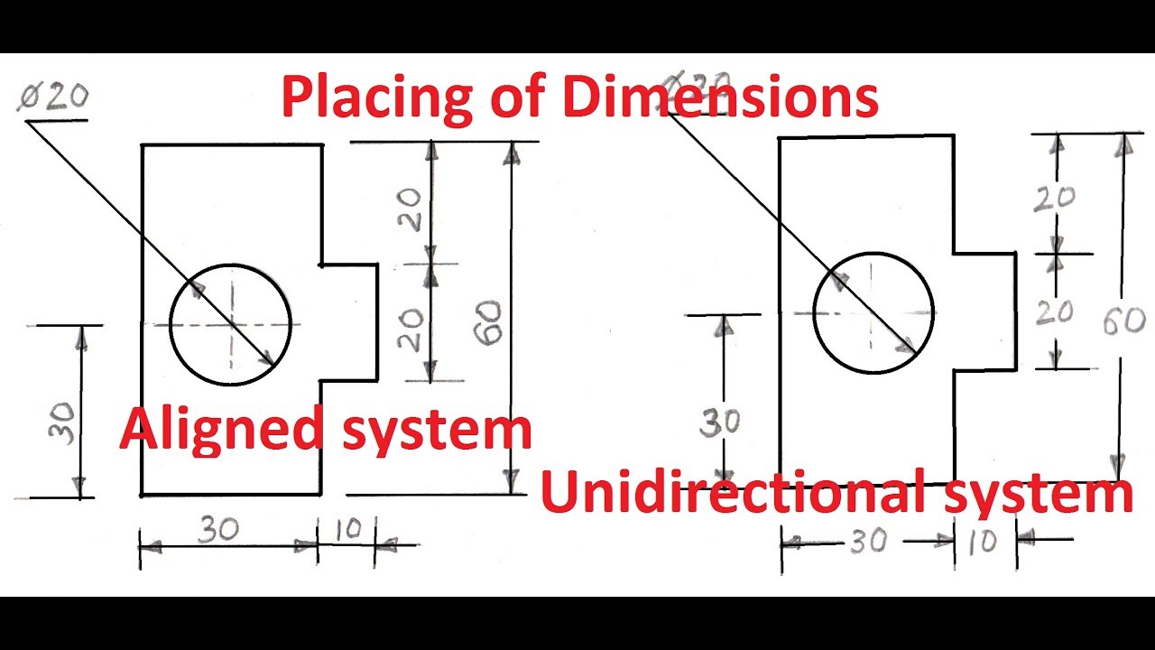
Beautiful Sketch two basic drawing dimensioning types of aligned
Click smart dimension (dimensions/relations toolbar) or click tools > dimensions > smart. The drawing should define a part without specifying manufacturing methods. Dimensions and tolerances and inspection. Web dimension and extension lines are used to indicate the sizes of features on a drawing. A dimension, usually without a tolerance, that is used for informational purposes only.

How to prepare a technical drawing for CNC machining Hubs
These notations are specified in asme y14.5 the dimensioning and. Dimensions shall be selected and arranged to suit the function and mating relationship of a part and shall not be subject to more than one interpretation. Web reference dimensions are shown on a drawing as a value embedded with parentheses. An alternate method is to follow the dimension with “reference”.
Components Of The Drawing Sheet.
A dimension, usually without a tolerance, that is used for informational purposes only. Web the use of reference dimensions on a drawing should be minimized. Web to add a reference dimension: In a drawing view, click the items you want to dimension.
Click Smart Dimension (Dimensions/Relations Toolbar) Or Click Tools, Dimensions, Smart.
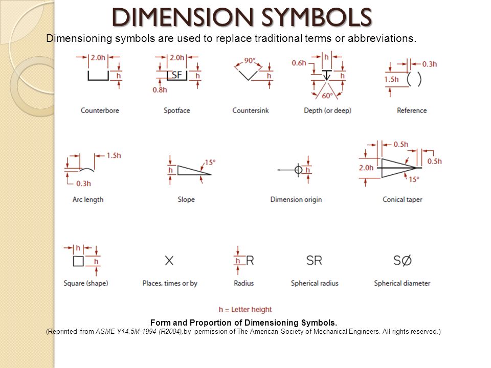
(.250) gd&t reference & training books: Basic requirements for dimensioning in part drawings. Web dimensioning of part drawings. Web the method for identifying a reference dimension (or reference data) on drawings is to enclose the dimension (or data) within parentheses.
There Is No Gd&T Symbol For A Reference Dimension.
Click smart dimension (dimensions/relations toolbar) or click tools > dimensions > smart. Point to the silhouette edge, and when the pointer appears, click to dimension. A reference dimension is a repeat of a dimension or is derived from other values on the drawing or related drawings. It does not govern production or inspection operations.
These Are Called Out On A Drawing Using Parenthesis (I.e., 5.125).
Point to the silhouette edge, and when the pointer appears, click to dimension. Web to add a reference dimension: To learn the basics of gd&t, check out our gd&t 101 article which includes the definitions and utilization of: There is no gd&t symbol for a reference measuring.