Single Line Drawing Symbols
Single Line Drawing Symbols - Web some common symbols used in electrical single line diagrams include: Represented by a circle with a horizontal line through it. You need to create a drafting view and you also need to select a 1:1 scale. Web these symbols include those representing transformers, circuit breakers, switches, motors, generators, resistors, capacitors, and many more. Electrical single line and schematic symbols 0.00 kb 692 downloads. Of course, the symbol must also include written text showing the. They are used to represent and communicate the structure and connections within an electrical system in a simplified and standardized manner. Incoming main fuses, cutouts, switches, and main/tie breakers. You cannot draw this directly in your model or on sheets. A single line diagram is method of simplified representation of a three phase power system.
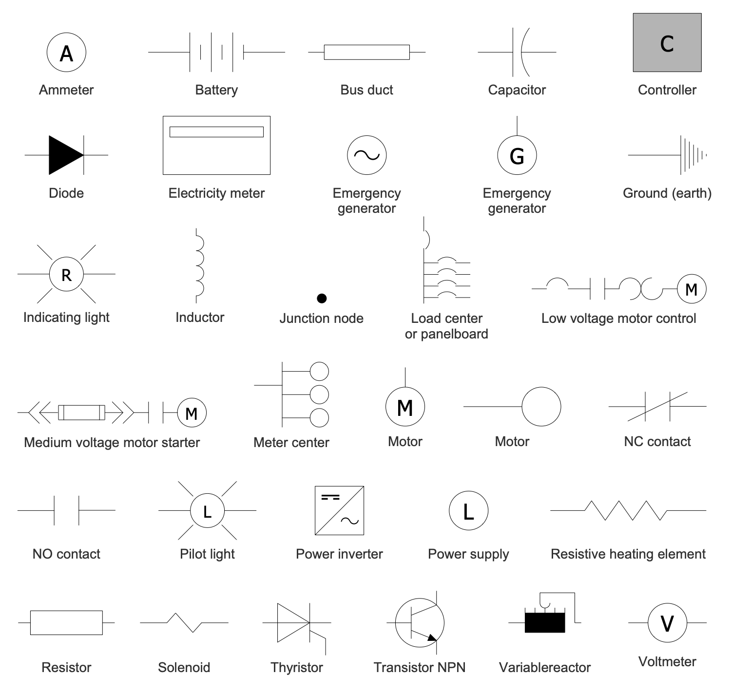
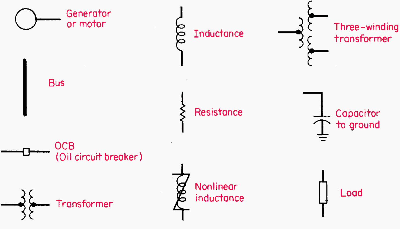
Simplicatoin in a single line diagrams. Web these symbols include those representing transformers, circuit breakers, switches, motors, generators, resistors, capacitors, and many more. They are used to represent and communicate the structure and connections within an electrical system in a simplified and standardized manner. It will have one single line shown for bus (or cable) to represent all three phases. It represents a passive component that limits the flow of electric current. It is used to store and release electrical charge. Electrical one line diagram symbols. As per the above switchgear definition, it can be break up to different parts as follows: “a diagram which shows, by means of single lines and graphic symbols, the course of an electric circuit or system of circuits and the component devices or parts used therein.” Web by r jagan mohan rao.
It is used to store and release electrical charge. A single line diagram is method of simplified representation of a three phase power system. This symbol is used to show the presence of a power source. Of course, the symbol must also include written text showing the. In this post you’ll learn what is single line diagram and why do we need it. Listed here are 20 sld symbols for the most important electrical and electronic engineering components. The symbols are connected by lines that represent the conductors that carry the power through the system. It represents a passive component that limits the flow of electric current. Web in a single line diagram, you’ll see symbols that represent things like generators, transformers, circuit breakers, and switches. All proper symbols shall be used.

Single Line Diagram Symbols Electrical Engineering
Represented by a circle with a horizontal line through it. It will have one single line shown for bus (or cable) to represent all three phases. Electrical single line and schematic symbols 0.00 kb 692 downloads. Sld must be started with an index, legend, page references. Incoming lines showing voltage and size.

iec electrical one line diagram symbols Wiring Diagram
The resistor symbol is a zigzag line, typically with two terminals. Electrical one line diagram symbols. Incoming lines showing voltage and size. A typical package of single line diagram shall include: In this post you’ll learn what is single line diagram and why do we need it.

The Ultimate Guide to Single Line Diagram Symbols Everything You Need
It will have one single line shown for bus (or cable) to represent all three phases. Represented by a circle with a vertical line and an arrow pointing outwards. Web some common symbols used in electrical single line diagrams include: It is a graphical representation of a circuit or system using standard electrical symbols. What is a single line diagram?
Electrical single line diagram symbols autocad valuepofe
\imp_slin and \met_slin (for metric users) user created schematic and single line symbols should be created in the \user_symb directory. Web 20 single line diagram symbols you need to know. As per the above switchgear definition, it can be break up to different parts as follows: These diagrams are used by engineers and technicians to design, build, and maintain power.
Oneline Diagrams Solution
What should be in a single line diagram (sld)? These diagrams are used by engineers and technicians to design, build, and maintain power systems. It represents a passive component that limits the flow of electric current. As per the above switchgear definition, it can be break up to different parts as follows: You can tell by the symbols that this.
How To Calculate and Draw a Single Line Diagram For The Power System EEP
It is used to store and release electrical charge. A single line diagram is method of simplified representation of a three phase power system. Today, we will explain the following: It will have one single line shown for bus (or cable) to represent all three phases. Web in a single line diagram, you’ll see symbols that represent things like generators,.

The Ultimate Guide to Understanding IEC Single Line Diagram Symbols
The capacitor symbol consists of two parallel lines, representing two plates, with curved lines connecting them. Web by r jagan mohan rao. Concept of a bus in single line diagram. It is used to store and release electrical charge. Simplicatoin in a single line diagrams.
![[DIAGRAM] Ansi Single Line Diagram Symbols FULL Version HD Quality](https://instrumentationtools.com/wp-content/uploads/2018/07/Single-Line-Diagram.png)
[DIAGRAM] Ansi Single Line Diagram Symbols FULL Version HD Quality
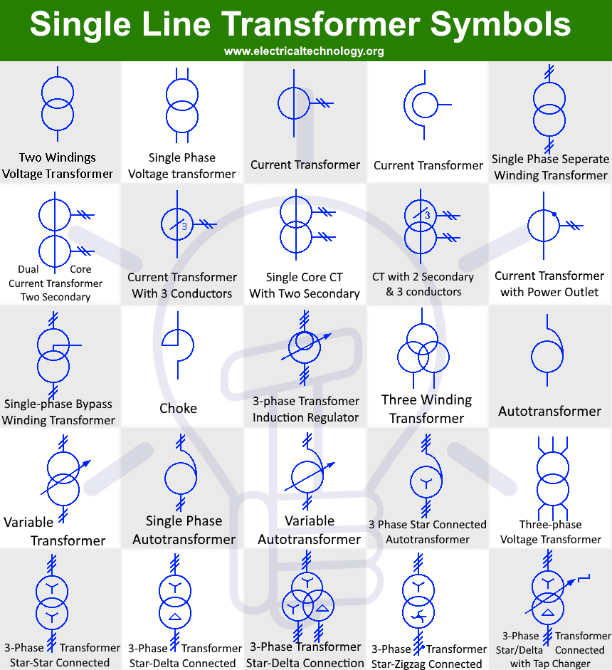
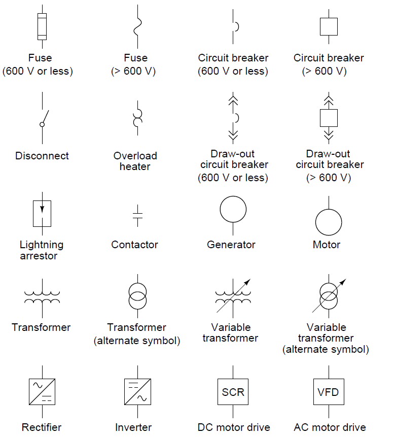
\imp_slin and \met_slin (for metric users) user created schematic and single line symbols should be created in the \user_symb directory. The resistor symbol is a zigzag line, typically with two terminals. Incoming main fuses, cutouts, switches, and main/tie breakers. Sld must be started with an index, legend, page references. Web single line diagram symbols:
Single Line Diagram Symbols Iec
\imp_slin and \met_slin (for metric users) user created schematic and single line symbols should be created in the \user_symb directory. The icon menus for schematic symbols can be found on the elecdes > symbols menu.</p> Incoming main fuses, cutouts, switches, and main/tie breakers. It is used to store and release electrical charge. Below is the csa z462 single line diagram.

Single Line Diagram Symbols Electrical Engineering
“control devices” check and/or regulate the flow of power. It is used to store and release electrical charge. Each symbol is designed to represent a specific electrical component or device, allowing for easy identification and interpretation. Web represnetatoin of load. The capacitor symbol consists of two parallel lines, representing two plates, with curved lines connecting them.
Concept Of A Bus In Single Line Diagram.
“a diagram which shows, by means of single lines and graphic symbols, the course of an electric circuit or system of circuits and the component devices or parts used therein.” Voltage regulators data, transformers data, switchgear data. Listed here are 20 sld symbols for the most important electrical and electronic engineering components. All proper symbols shall be used.
Sld Must Be Started With An Index, Legend, Page References.
Represented by a circle with a vertical line and an arrow pointing outwards. “control devices” check and/or regulate the flow of power. A typical package of single line diagram shall include: Web single line diagram symbols:
Below Is The Csa Z462 Single Line Diagram Definition:
Incoming lines showing voltage and size. You cannot draw this directly in your model or on sheets. What should be in a single line diagram (sld)? Web some common symbols used in electrical single line diagrams include:
Today, We Will Explain The Following:
Web represnetatoin of load. As per the above switchgear definition, it can be break up to different parts as follows: It is a graphical representation of a circuit or system using standard electrical symbols. You need to create a drafting view and you also need to select a 1:1 scale.