Surface Finish Callout On Drawing
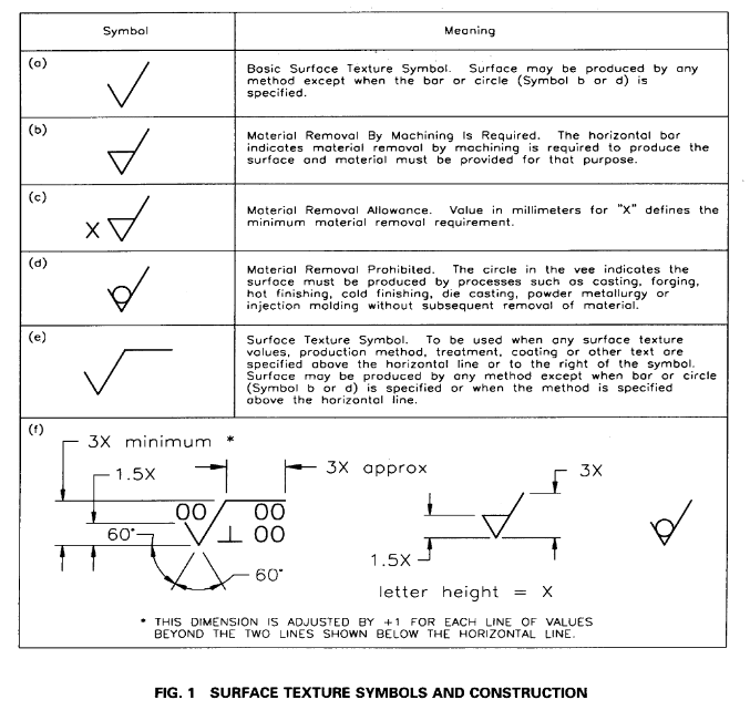
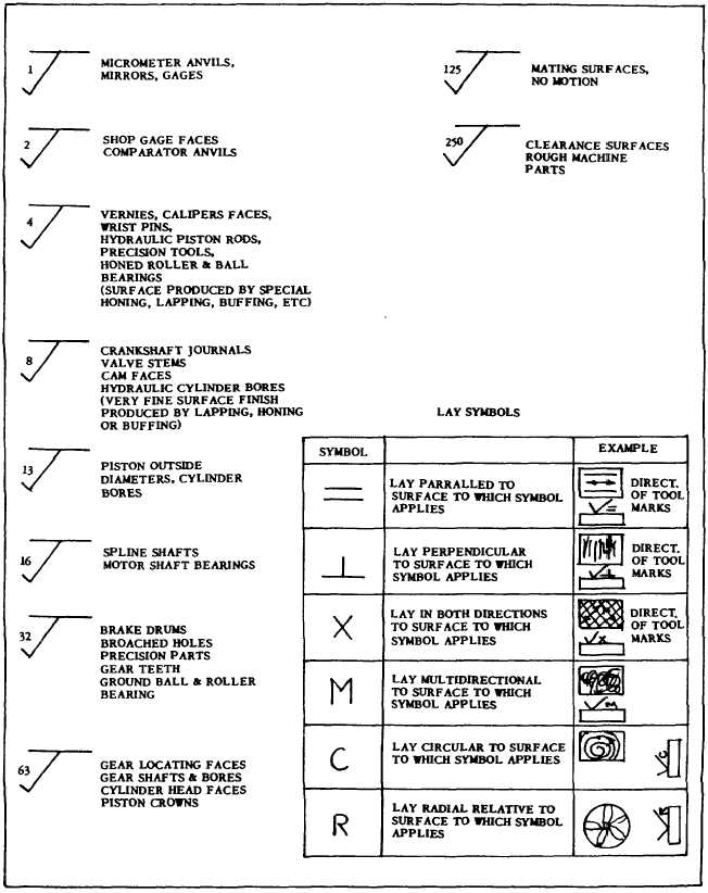
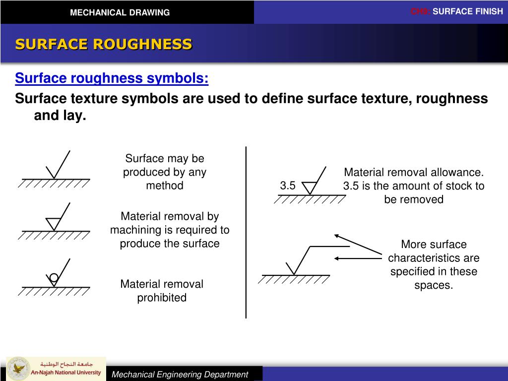
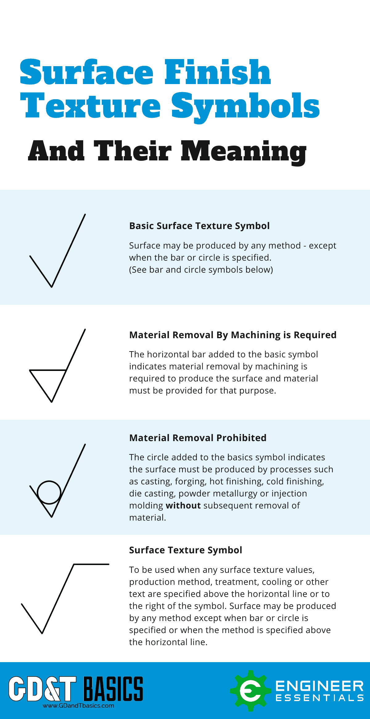
Surface Finish Callout On Drawing - The bis recommended symbols for indicating the surface finish are shown in table a. You can specify the surface texture of a part face by using a surface finish symbol. So how do you specify surface roughness on a drawing or a specification? Web what surface finish or roughness are required and how to indicate roughness in drawing? Surface finish is the term used to describe the texture of a surface, and it is sometimes used interchangeably with the term surface texture. Surface finish symbols are formed by combining the symbol and lay direction (direction of. A super handy surface finish “cheat sheet”: Surface roughness or roughness, is a measure of surface irregularities. So, now you can add this symbol for your required surface in the engineering drawing. Web what is surface finish?
Web it is suggested to indicate the surface roughness on drawing by symbols. You can specify the surface texture of a part face by using a surface finish symbol. Shop best sellersfast shippingdeals of the dayread ratings & reviews You can select the face in a part, assembly, or drawing document. Web iso surface finish symbols and callouts. So, now you can add this symbol for your required surface in the engineering drawing. Tips for improving surface finish. Web what surface finish or roughness are required and how to indicate roughness in drawing? Surface finish symbols and callout example. For the roughness values greater than 25μm, the symbol is used.
To specify surface finish use either the iso or ansi surface finish symbols. Web iso surface finish symbols and callouts. Shop best sellersfast shippingdeals of the dayread ratings & reviews Web what surface finish or roughness are required and how to indicate roughness in drawing? You can select the face in a part, assembly, or drawing document. The surface finish graphical symbol usage is defined in iso 1302:2002. A surface finish callout specifies the desired surface texture or quality for a particular part or component on an engineering drawing. The bis recommended symbols for indicating the surface finish are shown in table a. Surface finish symbols are formed by combining the symbol and lay direction (direction of. Gd&t specifies parameters like flatness, but these are not really surface finish.
PPT MECHANICAL DRAWING Chapter 9 SURFACE FINISH PowerPoint
How to measure surface roughness. Shop best sellersfast shippingdeals of the dayread ratings & reviews Web iso surface finish symbols and callouts. Surface finish symbols and callout example. Surface finish symbols are formed by combining the symbol and lay direction (direction of.
Surface Finish Symbols and Roughness Conversion Chart Tables
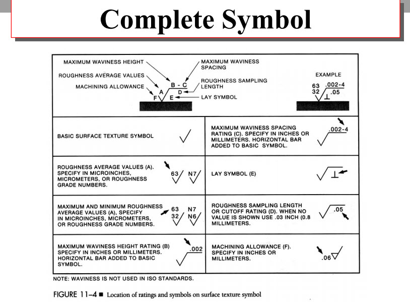
It is typically defined in terms of its roughness, waviness, and lay. Web ansi surface finish symbols and callouts. The bis recommended symbols for indicating the surface finish are shown in table a. Surface finish symbols and callout example. Tips for improving surface finish.
Surface Finish Symbols
You can select the face in a part, assembly, or drawing document. Web what is surface finish? Surface finish symbols are formed by combining the symbol and lay direction (direction of. Shop best sellersfast shippingdeals of the dayread ratings & reviews Ansi surface finish and callouts.
Surface finish
Web iso surface finish symbols and callouts. Surface finish is a term describing the texture of the surface of a printed object. Web it is suggested to indicate the surface roughness on drawing by symbols. Web surface finish symbols are graphical callouts to indicate surface texture and surface roughness for design parts manufactured by various manufacturing processes. So, now you.

Machining/surface finish symbol normal to line in drawings. — Onshape
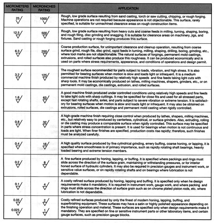
The bis recommended symbols for indicating the surface finish are shown in table a. Surface roughness is typically indicated on engineering drawings using a combination of symbols, grade numbers, and additional information. Requirements for surface finish are frequently found on technical drawings for mechanical parts, particularly where parts fit together tightly, move against each other, or. How to measure surface.
Surface Finish Symbols
In this article, we’ll explain the surface roughness symbols, indication, grade numbers, terminology and calculation. The bis recommended symbols for indicating the surface finish are shown in table a. Web what is surface finish? It is typically defined in terms of its roughness, waviness, and lay. To specify surface finish use either the iso or ansi surface finish symbols.
PPT MECHANICAL DRAWING Chapter 9 SURFACE FINISH PowerPoint
Web what surface finish or roughness are required and how to indicate roughness in drawing? Web surface finish symbols are graphical callouts to indicate surface texture and surface roughness for design parts manufactured by various manufacturing processes. Surface finish is a term describing the texture of the surface of a printed object. Gd&t specifies parameters like flatness, but these are.

Surface Finish Symbols for Engineering Drawings MECHHEART
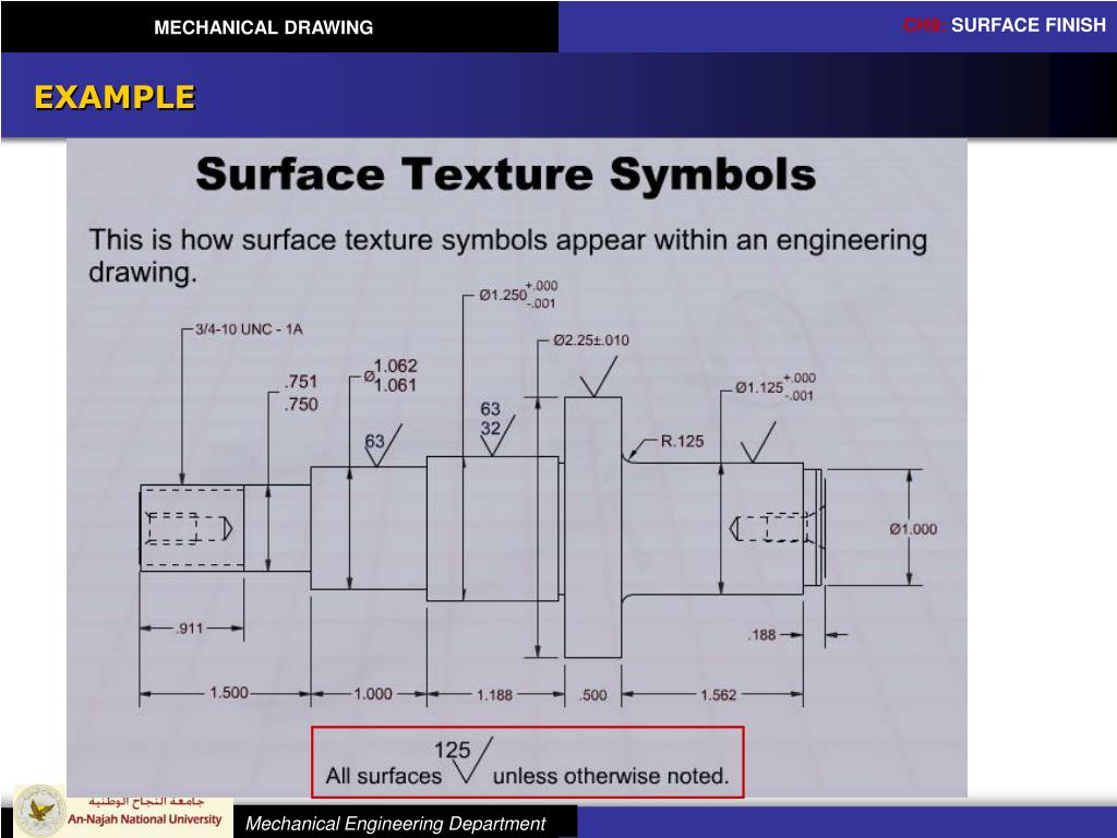
The callout might look like this: The surface finish graphical symbol usage is defined in iso 1302:2002. Surface finish is the term used to describe the texture of a surface, and it is sometimes used interchangeably with the term surface texture. Ansi surface finish and callouts. Surface roughness or roughness, is a measure of surface irregularities.

Surface Finish Call Out On Drawings
You can select the face in a part, assembly, or drawing document. For the roughness values greater than 25μm, the symbol is used. To specify surface finish use either the iso or ansi surface finish symbols. Web iso surface finish symbols and callouts. Surface finish symbols and callout example.
SurfaceFinishSymbolsChart1 GD&T Basics
It is typically defined in terms of its roughness, waviness, and lay. Surface finish symbols… surface finish symbols and callout example. You can select the face in a part, assembly, or drawing document. Someone will be along soon to finish this section! Surface finish symbols are formed by combining the symbol and lay direction (direction of.
A Super Handy Surface Finish “Cheat Sheet”:
Surface finish symbols… surface finish symbols and callout example. The callout might look like this: Requirements for surface finish are frequently found on technical drawings for mechanical parts, particularly where parts fit together tightly, move against each other, or. The bis recommended symbols for indicating the surface finish are shown in table a.
Web Iso Surface Finish Symbols And Callouts.
It is typically defined in terms of its roughness, waviness, and lay. Surface finish is the term used to describe the texture of a surface, and it is sometimes used interchangeably with the term surface texture. Surface finish is a term describing the texture of the surface of a printed object. So, now you can add this symbol for your required surface in the engineering drawing.
You Can Select The Face In A Part, Assembly, Or Drawing Document.
Ansi surface finish and callouts. Web ansi surface finish symbols and callouts. Tips for improving surface finish. To specify surface finish use either the iso or ansi surface finish symbols.
Surface Finish Symbols And Callout Example.
The surface finish graphical symbol usage is defined in iso 1302:2002. A surface finish callout specifies the desired surface texture or quality for a particular part or component on an engineering drawing. Someone will be along soon to finish this section! For the roughness values greater than 25μm, the symbol is used.