Symbol Engineering Drawing
Symbol Engineering Drawing - Web a convenient guide for geometric dimensioning and tolerancing (gd&t) symbols at your fingertips. The following tables show how to construct the symbols. We offer you our tips which we believe are useful for dispelling uncertainty by comparing the symbol with its graphic representation. Web engineering drawing abbreviations and symbols are used to communicate and detail the characteristics of an engineering drawing. Web the following is a short list of symbols that normally appear on a technical drawing and need understanding. The universal language works regardless of who you are working with. Radius can be for the inside and outside curved surface on the part. Web geometric dimensioning and tolerancing symbols you can either create your own library of gd&t symbols, or use one of autocad’s gd&t fonts to insert the symbols as text. Why not just use a 3d model? Web this page explains the 16 symbols used in gd&t, and the classification thereof.
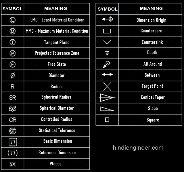
These symbols carry specific meanings and convey vital information about various facets of a design. Unlike a model, engineering drawings note much more specific information and requirements, such as: Here are the types of lines used in engineering drawing along with their details: The true position theory and the specification of tolerance zones are also explained. Web geometric dimensioning and tolerancing symbols you can either create your own library of gd&t symbols, or use one of autocad’s gd&t fonts to insert the symbols as text. Web basic types of symbols used in engineering drawings are countersink, counterbore, spotface, depth, radius, and diameter. This manual sets forth the minimum requirements acceptable at gsfc for the preparation of engineering drawings for flight hardware and ground support systems. We offer you our tips which we believe are useful for dispelling uncertainty by comparing the symbol with its graphic representation. The following tables show how to construct the symbols. Note the comparison with the iso standards.
Why not just use a 3d model? It is more than simply a drawing, it is a graphical language that communicates ideas and information. 81k views 5 years ago engineering. Some of these symbols are also used in tolerance specifications. Many of the definitions are not official asme, ansi or iso terminology. Web the purpose of this guide is to give you the basics of engineering sketching and drawing. Web geometric dimensioning and tolerancing symbols you can either create your own library of gd&t symbols, or use one of autocad’s gd&t fonts to insert the symbols as text. Web engineering drawing abbreviations and symbols are used to communicate and detail the characteristics of an engineering drawing. Web engineering drawing is a graphical representation of an object or structure, which is used to communicate design and manufacturing details. General dimensioning symbols are shown first.

M&e Drawing Symbols Back To Basics Komseq
We will treat “sketching” and “drawing” as one. It is more than simply a drawing, it is a graphical language that communicates ideas and information. Why not just use a 3d model? Web how to read an engineering drawing symbol. Web engineering and drafting personnel in the preparation, revision, and completion of engineering drawings.

Mechanical Engineering Drawing Symbols Pdf Free Download at
It is more than simply a drawing, it is a graphical language that communicates ideas and information. Note the comparison with the iso standards. Radius can be for the inside and outside curved surface on the part. Engineering drawing symbols are like a secret language that only engineers can decode. Web engineering drawing abbreviations and symbols are used to communicate.
Engineering Drawing Symbols List Chart Explain Mechanical Drawing
The true position theory and the specification of tolerance zones are also explained. “learning gd&t from scratch,” provided by keyence, walks you through the basics of geometric dimensioning and tolerancing, datums, and measurements by coordinate measuring. Unlike a model, engineering drawings offer more specific detail and requirements, such as: “sketching” generally means freehand drawing. 1.2 the symbols are presented in.

Engineering Drawing Symbols And Their Meanings Pdf at GetDrawings
Click on the links below to learn more about each gd&t symbol or concept, and be sure to download the free wall chart for a quick reference when at your desk or on the shop floor. These symbols carry specific meanings and convey vital information about various facets of a design. Web this chapter will introduce the five common categories.

How To Read Architectural Drawings Symbols The Architect
The reasons for using geometric dimensioning and tolerancing (gd&t) are: Web this page explains the 16 symbols used in gd&t, and the classification thereof. Some of these symbols are also used in tolerance specifications. It is more than simply a drawing, it is a graphical language that communicates ideas and information. Web engineering drawing symbols are simple to pick up.

Engineering Drawing Symbols And Their Meanings Pdf at PaintingValley
Web a convenient guide for geometric dimensioning and tolerancing (gd&t) symbols at your fingertips. The true position theory and the specification of tolerance zones are also explained. 81k views 5 years ago engineering. Web the purpose of this guide is to give you the basics of engineering sketching and drawing. Click on the links below to learn more about each.

Engineering Drawing Symbols List Chart Explain Mechanical Drawing
Learn the ins and outs of engineering drawing standards, such as iso and ansi, which govern the symbols, abbreviations, and notations. Web it establishes symbols, rules, definitions, requirements, defaults, and recommended practices for stating and interpreting gd&t and related requirements for use on engineering drawings, models defined in digital data files, and in related documents. Some of these symbols are.

Technical Drawing Symbols And Their Meanings Design Talk
The table shows dimensioning symbols found on engineering and mechanical drawings. Web how to read an engineering drawing symbol. 1.2 the symbols are presented in two groups for easier use of this section as a reference. We offer you our tips which we believe are useful for dispelling uncertainty by comparing the symbol with its graphic representation. The universal language.

Engineering Drawing Symbols And Their Meanings Pdf at PaintingValley
Unlike a model, engineering drawings offer more specific detail and requirements, such as: Web engineering drawing symbols are simple to pick up and use once you understand how to read them. We will treat “sketching” and “drawing” as one. Web it establishes symbols, rules, definitions, requirements, defaults, and recommended practices for stating and interpreting gd&t and related requirements for use.

Engineering Drawing Symbols And Their Meanings Pdf at PaintingValley
Many of the definitions are not official asme, ansi or iso terminology. Web engineering drawing abbreviations and symbols are used to communicate and detail the characteristics of an engineering drawing. Web gd&t symbol charts for engineering drawing & drafting. Some of these symbols are also used in tolerance specifications. It is more than simply a drawing, it is a graphical.
Web It Establishes Symbols, Rules, Definitions, Requirements, Defaults, And Recommended Practices For Stating And Interpreting Gd&T And Related Requirements For Use On Engineering Drawings, Models Defined In Digital Data Files, And In Related Documents.
This is just an introduction. It is a language of its own, with various types of lines and symbols used to convey specific information. Web engineering drawing abbreviations and symbols are used to communicate and detail the characteristics of an engineering drawing. Click on the links below to learn more about each gd&t symbol or concept, and be sure to download the free wall chart for a quick reference when at your desk or on the shop floor.
Note The Comparison With The Iso Standards.
This manual sets forth the minimum requirements acceptable at gsfc for the preparation of engineering drawings for flight hardware and ground support systems. The following are definitions commonly used throughout industry when discussing gd&t or composing engineering drawing notes. Unlike a model, engineering drawings offer more specific detail and requirements, such as: Radius can be for the inside and outside curved surface on the part.
Many Of The Definitions Are Not Official Asme, Ansi Or Iso Terminology.
We will treat “sketching” and “drawing” as one. Web gd&t symbol charts for engineering drawing & drafting. Web this page explains the 16 symbols used in gd&t, and the classification thereof. It is more than simply a drawing, it is a graphical language that communicates ideas and information.
Here Are More Commonly Used Engineering Drawing Symbols And Design Elements As Below.
It is a system of symbols and standards used by engineers to provide manufacturing information to the production team. “learning gd&t from scratch,” provided by keyence, walks you through the basics of geometric dimensioning and tolerancing, datums, and measurements by coordinate measuring. Any needed height h 2 h h 2 h 60° 2 h identification letter datum feature symbol datum target symbol target point and. Most symbols have been in y14.5 since at least 1994.