Symbol Mechanical Drawing
Symbol Mechanical Drawing - True position theory (size value in rectangular frame) They are also used to show the fillets given to strengthen the edges at connecting faces. Web a good design drawing can indicate all the details needed to produce a mechanical cnc milling part in an easy way. Because there is no large space on a drawing to contain all the text to illustrate the image, abbreviations, and symbols are often used in engineering drawings to communicate the characteristics of the product to be. As an integral part of cad/cam technology, cnc design is used to develop and produce products. Two methods of dimensioning are in common use. Once you familiarise yourself with these features, you’ll be able to trace the lines in a system to understand specific components and the overall function in the case of pfds and p&ids. Read this first to find out crucial information about the drawing, including: Users reported that in inventor drawing, moving text notes with symbol annotation (like sketch symbols or surface symbols) is inconsistent. Web geometric dimensioning and tolerancing symbols you can either create your own library of gd&t symbols, or use one of autocad’s gd&t fonts to insert the symbols as text.
Any needed height h 2 h h 2 h 60° 2 h identification letter datum feature symbol datum target symbol target point and. Unidirectional, the dimensions are written horizontally. Web the technical engineering drawing abbreviations we outline here are the terms used in the manufacturing (include precision cnc machining and more) and inspection of parts and assemblies. Mechanical design is an important step in creating and designing mechanical elements, components, products, and systems. Because there is no large space on a drawing to contain all the text to illustrate the image, abbreviations, and symbols are often used in engineering drawings to communicate the characteristics of the product to be. Engineers, draftsmen, contractors, and fabricators use symbols, terms,. Read this first to find out crucial information about the drawing, including: Almost everything communicated on a set of mechanical documents uses a symbol, a term, or an abbreviation. Dimensioning and tolerancing with 45 elements; Web a good design drawing can indicate all the details needed to produce a mechanical cnc milling part in an easy way.
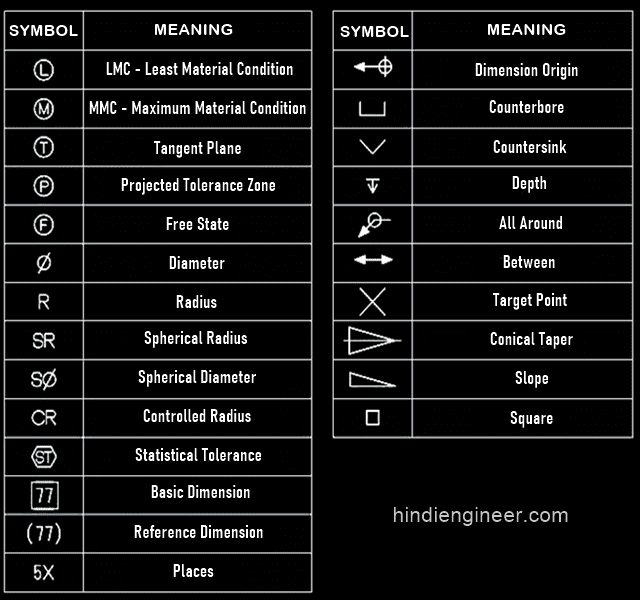
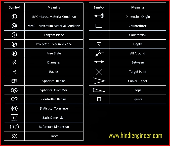
Dimensioning and tolerancing with 45 elements; Gd&t is used to define the nominal (theoretically. For example, ⌀ 10 4x eql spaced on bc means drill four holes of 10mm diameter equally spaced around the bolt circle. Web senga's mechanical reinvention has prolonged his absence from the club. Common abbreviations include ac (alternating current), dc (direct current), fab (fabrication), and ld (load). A radius dimension is preceded by an `r´. B) if the surface roughness is obtained by removing the. Web gd&t drawings and symbols. Smartdraw works in both us/imperial and metric standards of measure and also allows you to customize the scale of your mechanical drawing. Classification and symbols of geometric tolerance characteristics.
Mechanical Engineering Symbols Cadbull
Read this first to find out crucial information about the drawing, including: Web engineering drawing abbreviations and symbols are used to communicate and detail the characteristics of an engineering. These symbols can include lines, circles, squares, rectangles, and other shapes. Ala hijazi engineering working drawings basics page 10 of 22. Arcs are also dimensioned on drawing with a radius.

Technical Drawing Symbols And Their Meanings Design Talk
Web geometric dimensioning and tolerancing symbols you can either create your own library of gd&t symbols, or use one of autocad’s gd&t fonts to insert the symbols as text. [4] the name and contact information for the company producing or distributing the part. They are also used to show the fillets given to strengthen the edges at connecting faces. Web.

Mechanical Drawing Symbols Mathematics Symbols Process Flow Diagram
Web mechanical engineering solution — 8 libraries are available with 602 commonly used mechanical drawing symbols in mechanical engineering solution, including libraries called bearings with 59 elements of roller and ball bearings, shafts, gears, hooks, springs, spindles and keys; The title block appears either at the top or bottom of an engineering drawing. Classification and symbols of geometric tolerance characteristics..
Engineering Drawing Symbols List Chart Explain Mechanical Drawing
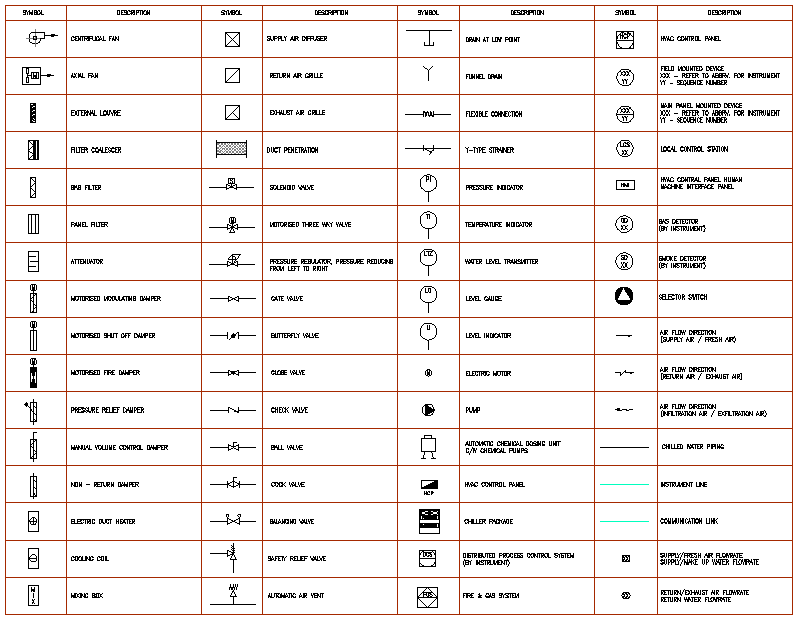
Aerospace series — graphic symbols for schematic drawings of hydraulic and pneumatic systems and components. Mechanical drawing symbols are used to represent different components in a mechanical system. True position theory (size value in rectangular frame) Web engineering drawing abbreviations and symbols. Users reported that in inventor drawing, moving text notes with symbol annotation (like sketch symbols or surface symbols).

Mechanical Engineering Drawing Symbols Pdf Free Download at
Arcs are also dimensioned on drawing with a radius. Web the table shows dimensioning symbols found on engineering and mechanical drawings. They are also used to show the fillets given to strengthen the edges at connecting faces. Most symbols have been in y14.5 since at least 1994. Toleranced characteristics and symbols — examples of indication and interpretation.

Mechanical Engineering
[4] the name and contact information for the company producing or distributing the part. You can even flip between scales on the fly. Web these abbreviations can be found on engineering drawings such as mechanical, electrical, piping and plumbing, civil, and structural drawings. Mechanical l earning mechanical terminology and symbols is vital to understanding mechanical drawings and designs. Web also.

Mechanical Engineering Drawing Symbols Pdf Free Download at
Common abbreviations include ac (alternating current), dc (direct current), fab (fabrication), and ld (load). Mechanical l earning mechanical terminology and symbols is vital to understanding mechanical drawings and designs. Ala hijazi engineering working drawings basics page 10 of 22. For example, ⌀ 10 4x eql spaced on bc means drill four holes of 10mm diameter equally spaced around the bolt.

Mechanical Drawing Symbols
Ala hijazi engineering working drawings basics page 10 of 22. After selecting many elements at once, all drawing annotations will move together. Web common mechanical drawing symbols. Dimensioning and tolerancing with 45 elements; Gd&t is used to define the nominal (theoretically.
Mechanical Engineering Drawing Symbols Pdf Free Download at
Web also called by various other names, such as engineering change order (eco), engineering change notice (ecn), drawing change notice (dcn), and so on. [4] the name and contact information for the company producing or distributing the part. Aerospace series — graphic symbols for schematic drawings of hydraulic and pneumatic systems and components. Mechanical l earning mechanical terminology and symbols.

Mechanical Engineering Drawing Symbols Pdf Free Download at
Ala hijazi engineering working drawings basics page 10 of 22. Users reported that in inventor drawing, moving text notes with symbol annotation (like sketch symbols or surface symbols) is inconsistent. True position theory (size value in rectangular frame) Gd&t is used to define the nominal (theoretically. Web graphical symbols for use on mechanical engineering and construction drawings, diagrams, plans, maps.
To Read An Ed, You Must First Become Familiar With The Various Symbols, Abbreviations, And Diagram Basics.
Classification and symbols of geometric tolerance characteristics. True position theory (size value in rectangular frame) Toleranced characteristics and symbols — examples of indication and interpretation. Check the title block for basic information about the drawing.
Two Methods Of Dimensioning Are In Common Use.
Web gd&t drawings and symbols. Geometric tolerances are specified using symbols on a drawing. Mechanical drawing symbols are used to represent different components in a mechanical system. Gd&t is used to define the nominal (theoretically.
For Example, R6 Means The Circle Has A Radius Of 6Mm.
Because there is no large space on a drawing to contain all the text to illustrate the image, abbreviations, and symbols are often used in engineering drawings to communicate the characteristics of the product to be. Ala hijazi engineering working drawings basics page 10 of 22. Web the technical engineering drawing abbreviations we outline here are the terms used in the manufacturing (include precision cnc machining and more) and inspection of parts and assemblies. Its precision, clarity, and thoughtfulness play a vital role in the development and manufacturing of a wide range of mechanical products and systems.
Users Reported That In Inventor Drawing, Moving Text Notes With Symbol Annotation (Like Sketch Symbols Or Surface Symbols) Is Inconsistent.
Smartdraw works in both us/imperial and metric standards of measure and also allows you to customize the scale of your mechanical drawing. Aligned, the dimensions are written parallel to their dimension line. Symbols or conventions used on the drawing and any additional information the designeror draftsmanfeltwas necessaryto understandthedrawing. After selecting many elements at once, all drawing annotations will move together.