Technical Drawing Isometric
Technical Drawing Isometric - The representation of the object in figure 2 is called an isometric drawing. Web put information in your drawings and diagrams into perspective with an isometric drawing. Whether you're a seasoned engineer or just starting your journey, this. Web in this article, we will offer you a complete guide to isometric projection in technical drawing, from the basic concepts to practical steps for its application. Web learning how to use illustrator to create isometric diagrams, set up isometric grids, and design isometric cubes are fundamental skills that you can build upon. Web isometric drawings, sometimes called isometric projections, are a good way of showing measurements and how components fit together. It uses a set of three equal angles to depict the object's height, width, and depth without distortion. Web this well explained tutorial video teaches easy methods on how to draw a isometric block in engineering drawing and technical drawing. Understanding the three main rules of isometric drawing is essential for precision and clarity in conveying complex concepts and structures. Web learn to draw isometric projections using these simple steps provided.
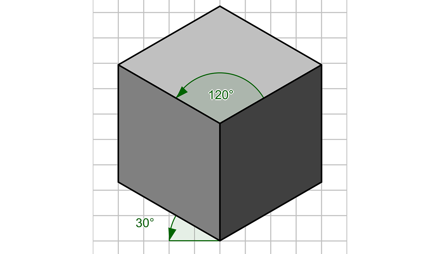
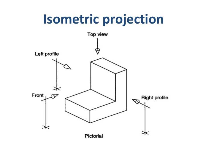
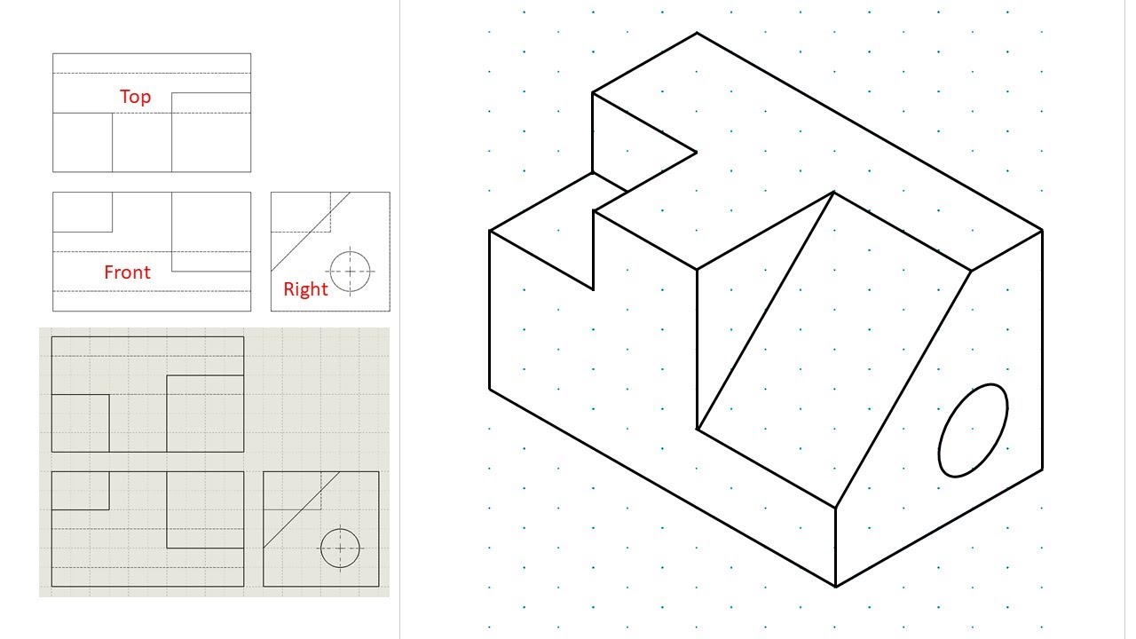
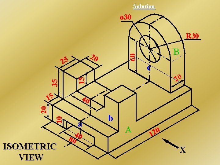
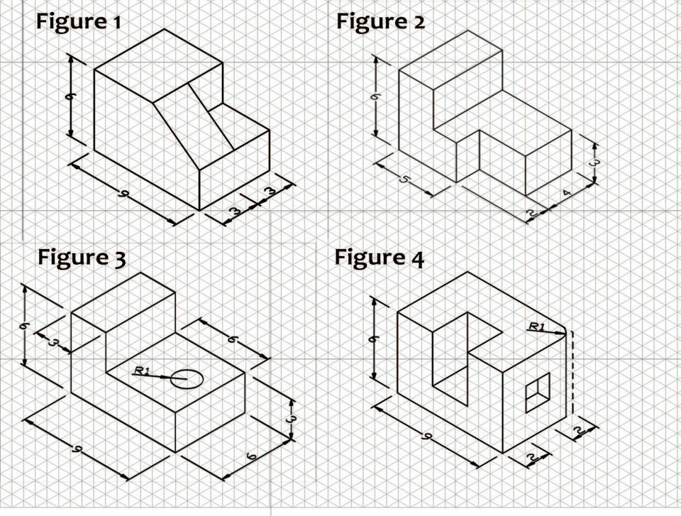
Isometric drawings, sometimes called isometric projections, are a good way of showing. Web isometric drawings are commonly used in technical drawing to show an item in 3d on a 2d page. When drawn under these guidelines, the lines parallel to these three axes are at their true (scale) lengths. Unlike perspective drawings, they don’t get smaller as the. Web in this comprehensive tutorial, we delve into the art of creating flawless isometric views using orthographic projections. The technique is intended to combine the illusion of depth, as in a perspective rendering, with the undistorted presentation of the object’s principal dimensions. In an isometric drawing, the object’s vertical lines are drawn vertically, and the horizontal lines in the width and depth planes are shown at 30 degrees to the horizontal. Discover how to master this technique and improve your technical drawing skills. Web identify views used in technical drawings including perspective, isometric, oblique, orthographic, plans, elevations, and sections. Web in an isometric drawing, the object’s vertical lines are drawn vertically, and the horizontal lines in the width and depth planes are shown at 30 degrees to the horizontal.
The technique is intended to combine the illusion of depth, as in a perspective rendering, with the undistorted presentation of the object’s principal dimensions. Unlike perspective drawings, they don’t get smaller as the. Discover how to master this technique and improve your technical drawing skills. Web isometric drawings, including piping symbols and various types of pipeline drawings, are vital in technical fields like engineering and design. Web identify views used in technical drawings including perspective, isometric, oblique, orthographic, plans, elevations, and sections. Web these best practices apply to 2d drafting and creating technical drawings from a 3d model. Web learn to draw isometric projections using these simple steps provided. Web in this article, we will offer you a complete guide to isometric projection in technical drawing, from the basic concepts to practical steps for its application. Web how to make an isometric drawing. Understanding the three main rules of isometric drawing is essential for precision and clarity in conveying complex concepts and structures.
Isometric drawing a designer's guide Creative Bloq
The technique is intended to combine the illusion of depth, as in a perspective rendering, with the undistorted presentation of the object’s principal dimensions. Web identify views used in technical drawings including perspective, isometric, oblique, orthographic, plans, elevations, and sections. Unlike perspective drawings, they don’t get smaller as the. Discover how to master this technique and improve your technical drawing.
Isometric Drawing, Projection Its Types, Methods.
Web isometric drawings are commonly used in technical drawing to show an item in 3d on a 2d page. The representation of the object in figure 2 is called an isometric drawing. Web how to make an isometric drawing. Web isometric drawings, including piping symbols and various types of pipeline drawings, are vital in technical fields like engineering and design..
Isometric view drawing example 1 (easy). Links to practice files in
Web these best practices apply to 2d drafting and creating technical drawings from a 3d model. The technique is intended to combine the illusion of depth, as in a perspective rendering, with the undistorted presentation of the object’s principal dimensions. Isometric drawings, sometimes called isometric projections, are a good way of showing. Create a single template that can be used.

Engineering Drawing Isometric Projections Example 2 YouTube
Create a single template that can be used for detail and assembly drawings compliant with asme or iso standards (depending on location). Discover how to master this technique and improve your technical drawing skills. Web these best practices apply to 2d drafting and creating technical drawings from a 3d model. Web learn to draw isometric projections using these simple steps.
Isometric Drawing at Explore collection of
Web i'll cover all the basics of isometric drawing for engineering and technical draw. Web how to make an isometric drawing. Web identify views used in technical drawings including perspective, isometric, oblique, orthographic, plans, elevations, and sections. Isometric drawings, sometimes called isometric projections, are a good way of showing. Web learn to draw isometric projections using these simple steps provided.
What is an Isometric Drawing? Types And Step To Draw
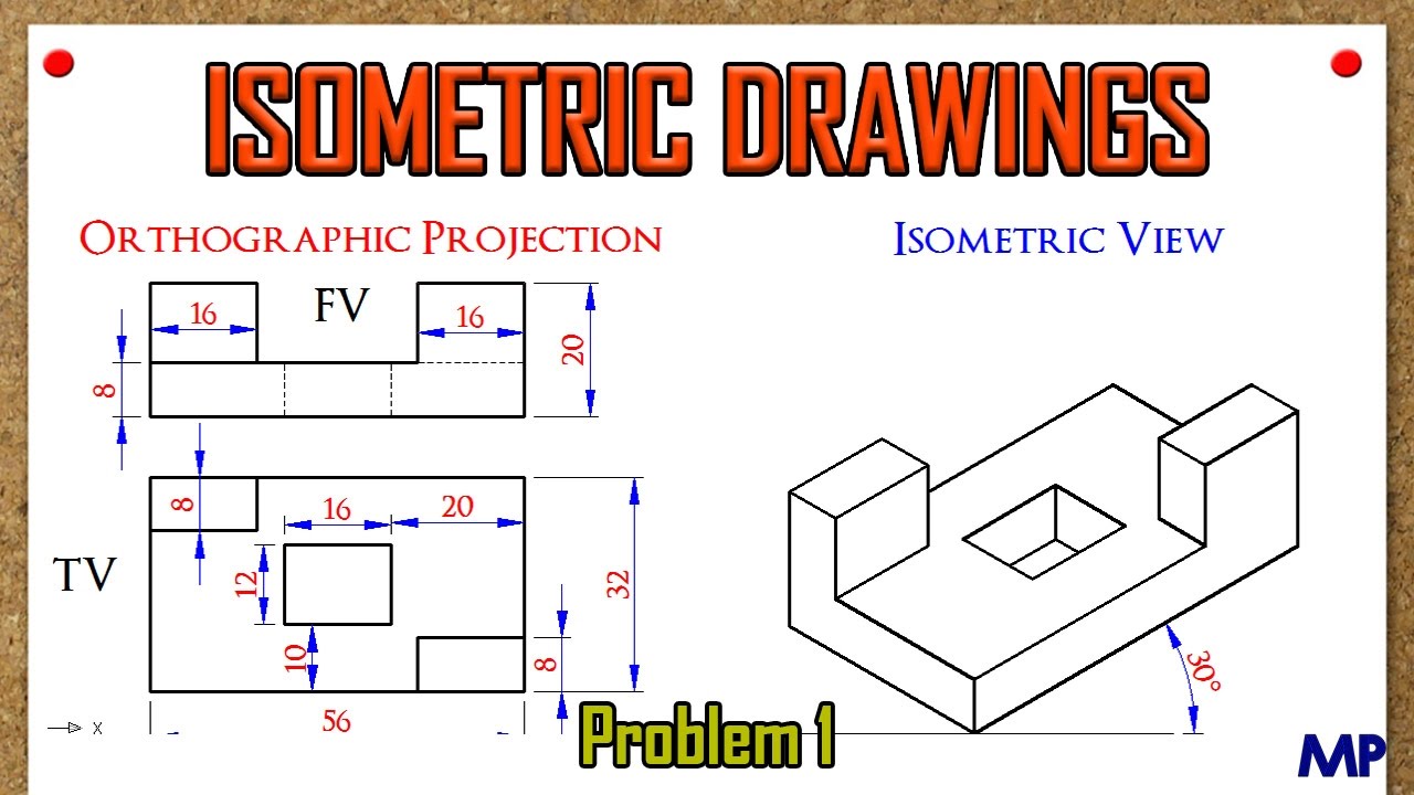
Web in this comprehensive tutorial, we delve into the art of creating flawless isometric views using orthographic projections. Web this well explained tutorial video teaches easy methods on how to draw a isometric block in engineering drawing and technical drawing. The technique is intended to combine the illusion of depth, as in a perspective rendering, with the undistorted presentation of.
1.0 Orthographic Sketching Practice Jonesboro High School Engineering
Web these best practices apply to 2d drafting and creating technical drawings from a 3d model. Web learning how to use illustrator to create isometric diagrams, set up isometric grids, and design isometric cubes are fundamental skills that you can build upon. Isometric drawings, sometimes called isometric projections, are a good way of showing. It is an axonometric projection in.
3 Views Of Isometric Drawing at Explore collection
Web isometric drawings, including piping symbols and various types of pipeline drawings, are vital in technical fields like engineering and design. The technique is intended to combine the illusion of depth, as in a perspective rendering, with the undistorted presentation of the object’s principal dimensions. It is an axonometric projection in which the three coordinate axes appear equally foreshortened and.
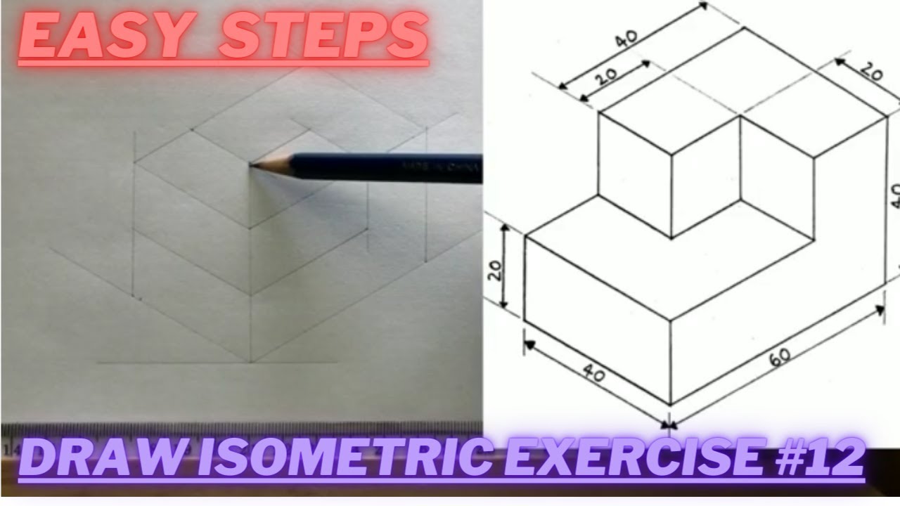
How to draw ISOMETRIC PROJECTIONS Technical Drawing Exercise 12
Web in this article, we will offer you a complete guide to isometric projection in technical drawing, from the basic concepts to practical steps for its application. One method is a “reductive” method which involves drawing a “bounding box” around what will ultimately become the final drawing and “cutting away” the unnecessary parts. Web isometric drawings, sometimes called isometric projections,.

Isometric Drawing For Beginners Pdf bmpi
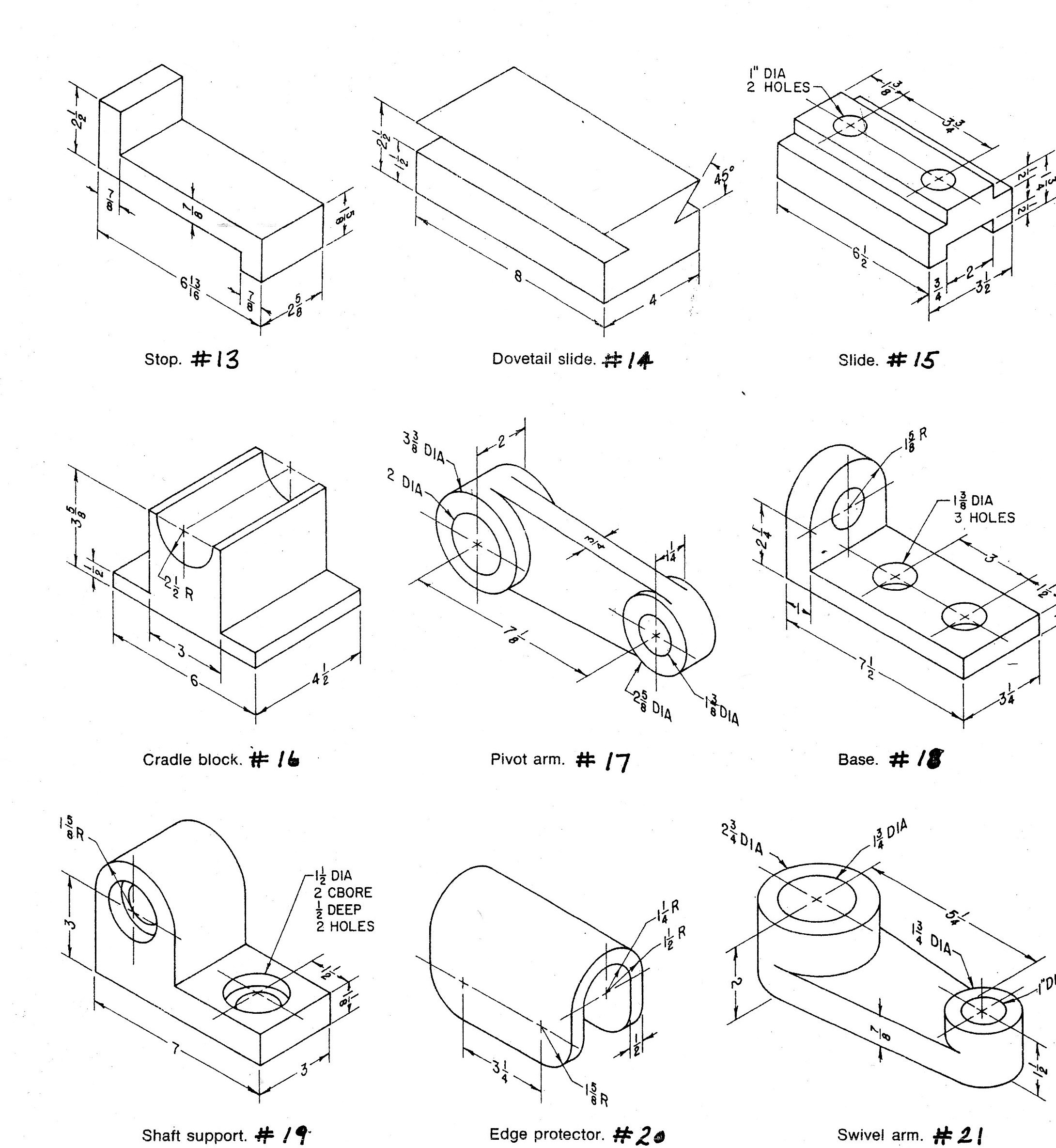
Isometric drawings, sometimes called isometric projections, are a good way of showing. One method is a “reductive” method which involves drawing a “bounding box” around what will ultimately become the final drawing and “cutting away” the unnecessary parts. To make an isometric drawing, start with an orthographic drawing or with the object itself. Web isometric drawings, sometimes called isometric projections,.
The Representation Of The Object In Figure 2 Is Called An Isometric Drawing.
One method is a “reductive” method which involves drawing a “bounding box” around what will ultimately become the final drawing and “cutting away” the unnecessary parts. Understanding the three main rules of isometric drawing is essential for precision and clarity in conveying complex concepts and structures. Web in an isometric drawing, the object’s vertical lines are drawn vertically, and the horizontal lines in the width and depth planes are shown at 30 degrees to the horizontal. It is an axonometric projection in which the three coordinate axes appear equally foreshortened and the angle between any two of them is 120 degrees.
It Uses A Set Of Three Equal Angles To Depict The Object's Height, Width, And Depth Without Distortion.
To make an isometric drawing, start with an orthographic drawing or with the object itself. Web identify views used in technical drawings including perspective, isometric, oblique, orthographic, plans, elevations, and sections. Web i'll cover all the basics of isometric drawing for engineering and technical draw. Web in this comprehensive tutorial, we delve into the art of creating flawless isometric views using orthographic projections.
Unlike Perspective Drawings, They Don’t Get Smaller As The.
Isometric drawings, sometimes called isometric projections, are a good way of showing. Web put information in your drawings and diagrams into perspective with an isometric drawing. Web isometric drawings are commonly used in technical drawing to show an item in 3d on a 2d page. Web in this article, we will offer you a complete guide to isometric projection in technical drawing, from the basic concepts to practical steps for its application.
Web Isometric Drawings, Sometimes Called Isometric Projections, Are A Good Way Of Showing Measurements And How Components Fit Together.
Web how to make an isometric drawing. Web this well explained tutorial video teaches easy methods on how to draw a isometric block in engineering drawing and technical drawing. Create a single template that can be used for detail and assembly drawings compliant with asme or iso standards (depending on location). Isometric drawings are easy once you learn the basic techniques.