Tolerance Drawing
Tolerance Drawing - Tolerances on technical drawings communicate the amount of variation permitted from a target dimension. They can be applied to several conditions, including linear dimensions, angular dimensions, external radius, chamfer heights, etc. Other measured values (such as temperature, humidity, etc.); Currently, we have 16 symbols for geometric tolerances, which are categorized according to the tolerance they specify. Web technical drawings often include notations such as “50 g6” or “17.5 h11/g8” to specify tolerances. Find your data faster with our fits and tolerance calculator. This is a minimally dimensioned drawing. Web the difference between the acceptable maximum and minimum dimensions given for a hole, shaft, or other feature is known as the tolerance. Why does the designer do this? Web hi guys, i need help on the requirement of inspecting individual piece parts features on to the assembly level in the same drawing.
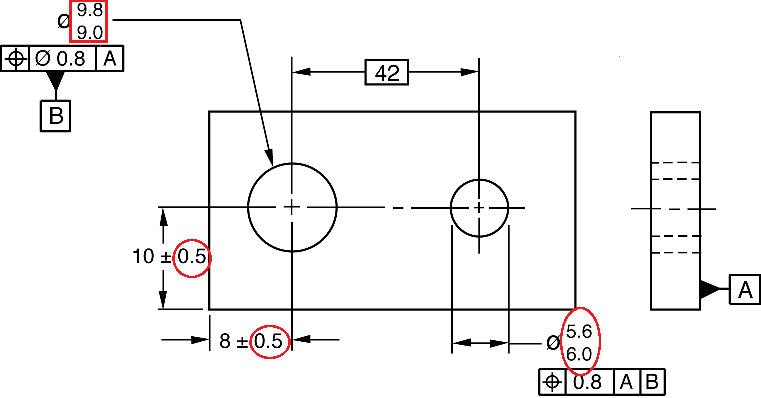
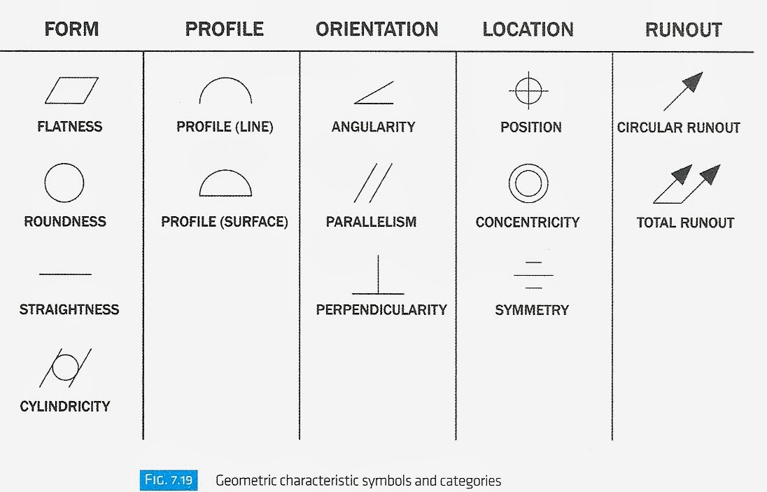
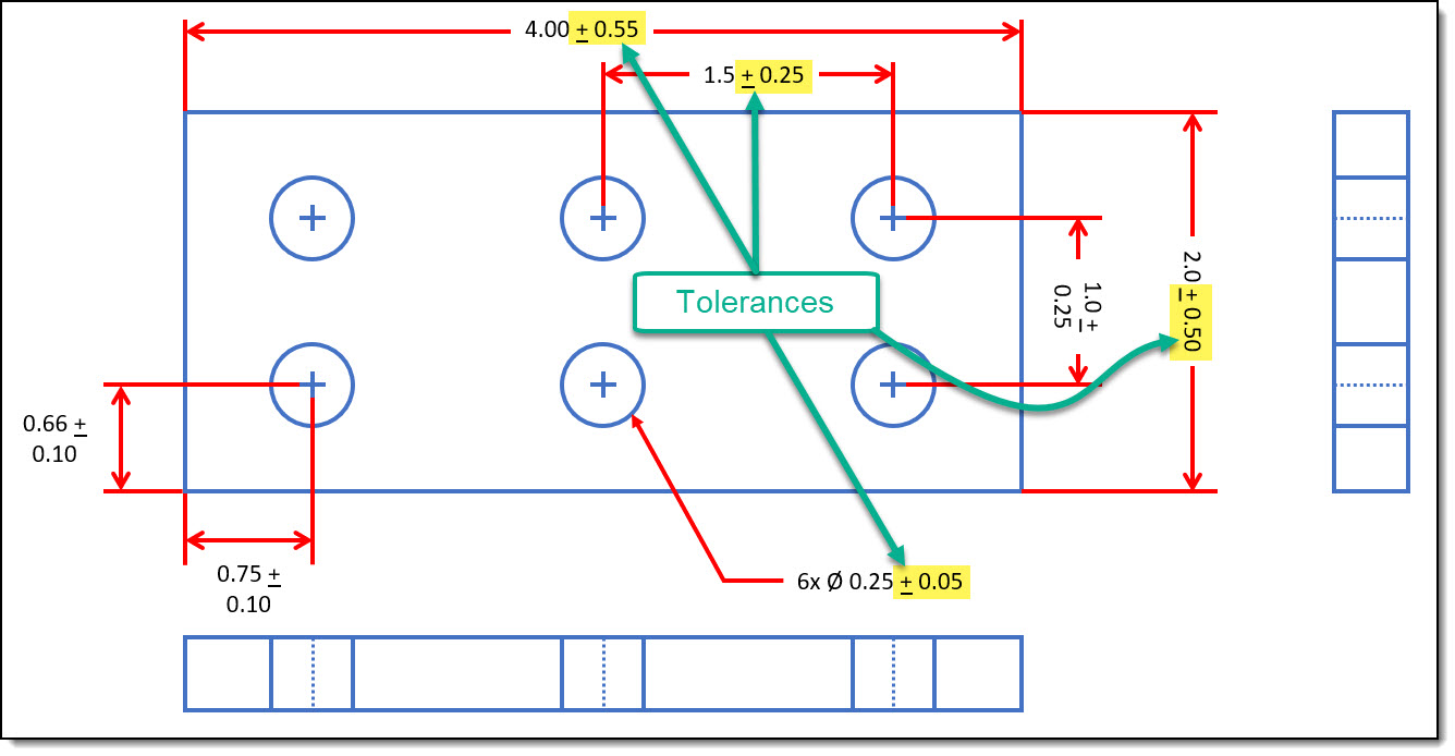
Through this method, y14.5 aims to improve quality, lower costs, and shorten deliveries wherever mechanical parts are designed or manufactured. Determining a positive or a negative dimension direction. Web it is the amount of variation allowed for any given dimension to achieve the proper function. Because it is impossible to make everything to an exact size, tolerances are used on production drawings to control the parts. Web geometric dimensioning and tolerancing is a set of rules and gd&t symbols used on a drawing to communicate the intent of a design, focusing on the function of the part. Tolerances on technical drawings communicate the amount of variation permitted from a target dimension. Classification and symbols of geometric tolerance characteristics. Engineering tolerances include dimension tolerance, shape. Web the tolerancing depicts the top left hole center to be located at 3 inches from the lower edge, plus or minus 0.005 inches and 1 inch from the left edge , plus 0.005 inches and minus zero inches. Part dimensions within the desired tolerances range are qualified.
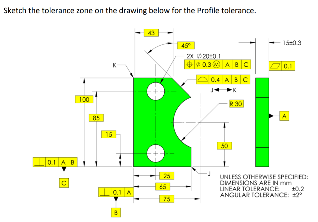
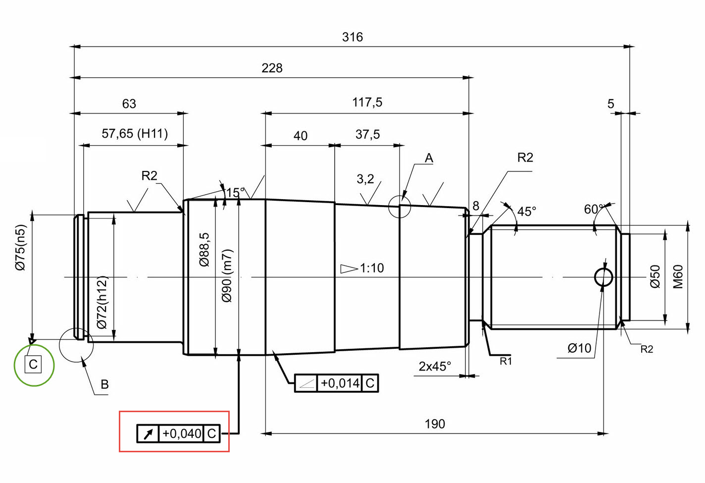
Green = prefered tolerance classes per iso 286. Web geometric dimensioning and tolerancing is a set of rules and gd&t symbols used on a drawing to communicate the intent of a design, focusing on the function of the part. Defining the distance to calculate. Using gd&t results in a more accurate design, larger tolerances for less important design features, and cost savings for manufacturing. Web technical drawings often include notations such as “50 g6” or “17.5 h11/g8” to specify tolerances. These tolerances are applicable in different conditions such as chamfer heights, linear dimensions, external radius, angular dimensions, etc. True position theory (size value in rectangular frame) Web geometric dimensioning and tolerancing (gd&t) is a system of symbols and standards used in engineering drawings and models to specify the required form, size, orientation, and location of parts and features. The following tolerance applies to all. Why does the designer do this?

international day for tolerance(November 16)drawing easy tolerance day
Web and tolerancing the shapes and locations of features on objects. Entry of the tolerances on the drawing. Using gd&t results in a more accurate design, larger tolerances for less important design features, and cost savings for manufacturing. Once the shape of a part is defined with an orthographic drawings, the size information is added also in the form of.

Tolerances A Brief Introduction EngineeringClicks
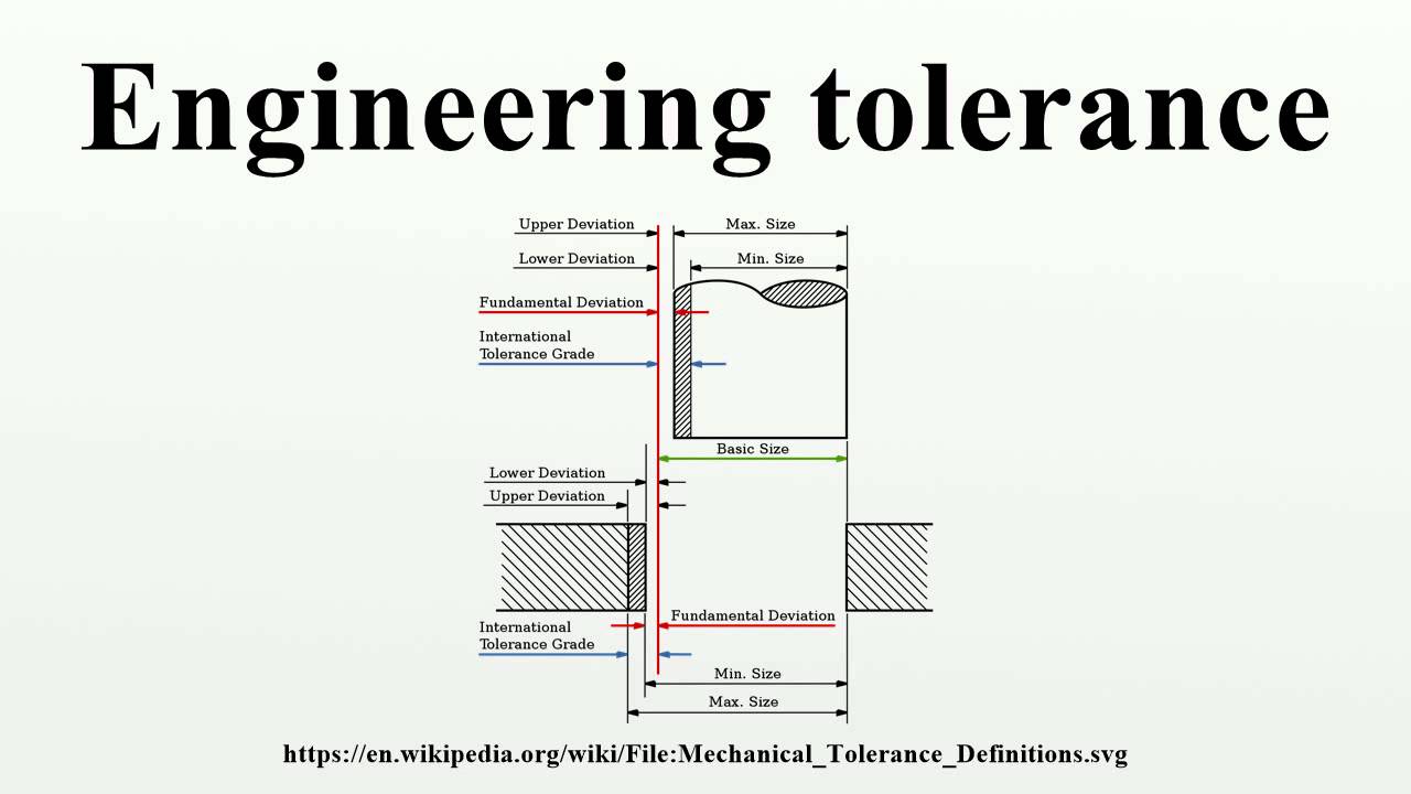
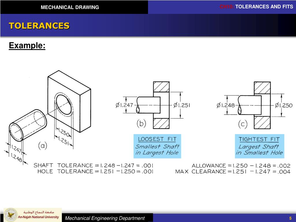
Find your data faster with our fits and tolerance calculator. Scope of the applying tolerances. Because it is impossible to make everything to an exact size, tolerances are used on production drawings to control the parts. Web geometric tolerances are specified using symbols on a drawing. In the example above the tolerance is 0.010 (that is, 2.005 − 1.995) inch.
Types Of Tolerance In Engineering Drawing at
Web engineering tolerance is the permissible limit or limits of variation in: The following tolerance applies to all. Dimensioning a drawing also identifies the tolerance (or accuracy) required for each dimension. Web geometric tolerances are specified using symbols on a drawing. The dimension without tolerances is known as the basic.
Specifying Tolerance in Engineering Drawings Techno FAQ
Through this method, y14.5 aims to improve quality, lower costs, and shorten deliveries wherever mechanical parts are designed or manufactured. Classification and symbols of geometric tolerance characteristics. Dimensioning a drawing also identifies the tolerance (or accuracy) required for each dimension. These are the kinds of tolerances most of us are used to seeing, before gd&t. Web geometric dimensioning and tolerancing.
ENGR 1304 Chapter 7 Tolerances
Defining the distance to calculate. Web and tolerancing the shapes and locations of features on objects. Web engineering tolerance is the permissible limit or limits of variation in: The dimension without tolerances is known as the basic. Web geometric dimensioning and tolerancing (gd&t or gd and t) is a language of symbols and standards designed and used by engineers and.
Tolerance Drawing at GetDrawings Free download
Web geometric dimensioning and tolerancing (gd&t or gd and t) is a language of symbols and standards designed and used by engineers and manufacturers to describe the shape (geometry) and size (dimensions) of a product and facilitate communication between entities working together to manufacture products. Tolerance functional features and their interrelations first, then move on to the rest of the.
PPT MECHANICAL DRAWING Chapter 10 TOLERANCES AND FITS PowerPoint
Dimensioning a drawing also identifies the tolerance (or accuracy) required for each dimension. Once the shape of a part is defined with an orthographic drawings, the size information is added also in the form of dimensions. We have a drawing which have 3 piece parts having holes with positional tolerances at piece part level and the assembly of those parts.

Examples of Determining the Tolerance on an Engineering Drawing? ED
Tolerance functional features and their interrelations first, then move on to the rest of the part. Web tolerance is the total amount a dimension may vary and is the difference between the upper (maximum) and lower (minimum) limits. When a part is designed, the cad model is designed exactly how we want the part to be. Web geometric dimensioning and.
Engineering Drawings & GD&T For the Quality Engineer
Scope of the applying tolerances. Web it is the amount of variation allowed for any given dimension to achieve the proper function. Web geometric dimensioning and tolerancing is a set of rules and gd&t symbols used on a drawing to communicate the intent of a design, focusing on the function of the part. When do we need tolerances? Praniewicz (nist).
Types Of Tolerance In Engineering Drawing at
Dimensioning a drawing also identifies the tolerance (or accuracy) required for each dimension. Defining the distance to calculate. The densely packed episode 8 manages to keep its many plates spinning and quickly build up a. Web technical drawings often include notations such as “50 g6” or “17.5 h11/g8” to specify tolerances. When a part is designed, the cad model is.
Find Your Data Faster With Our Fits And Tolerance Calculator.
This is a minimally dimensioned drawing. The densely packed episode 8 manages to keep its many plates spinning and quickly build up a. Web the difference between the acceptable maximum and minimum dimensions given for a hole, shaft, or other feature is known as the tolerance. Web what is a tolerance?
Green = Prefered Tolerance Classes Per Iso 286.
These are the kinds of tolerances most of us are used to seeing, before gd&t. Web and tolerancing the shapes and locations of features on objects. Web engineering tolerance is the permissible limit or limits of variation in: When do we need tolerances?
Web Tolerance Is The Total Amount A Dimension May Vary And Is The Difference Between The Upper (Maximum) And Lower (Minimum) Limits.
Web hi guys, i need help on the requirement of inspecting individual piece parts features on to the assembly level in the same drawing. Specific tighter or looser tolerances indicated in the drawing will then supersede the general tolerance. Determining a positive or a negative dimension direction. Currently, we have 16 symbols for geometric tolerances, which are categorized according to the tolerance they specify.
If You Take A Look At An Engineering Drawing, You Will Notice That There Are Always Limits, Or Tolerances, Placed On A Dimension.
Web by brandon john on august 3, 2021. Why does the designer do this? These tolerances are applicable in different conditions such as chamfer heights, linear dimensions, external radius, angular dimensions, etc. Tolerance functional features and their interrelations first, then move on to the rest of the part.