Weldment Drawing
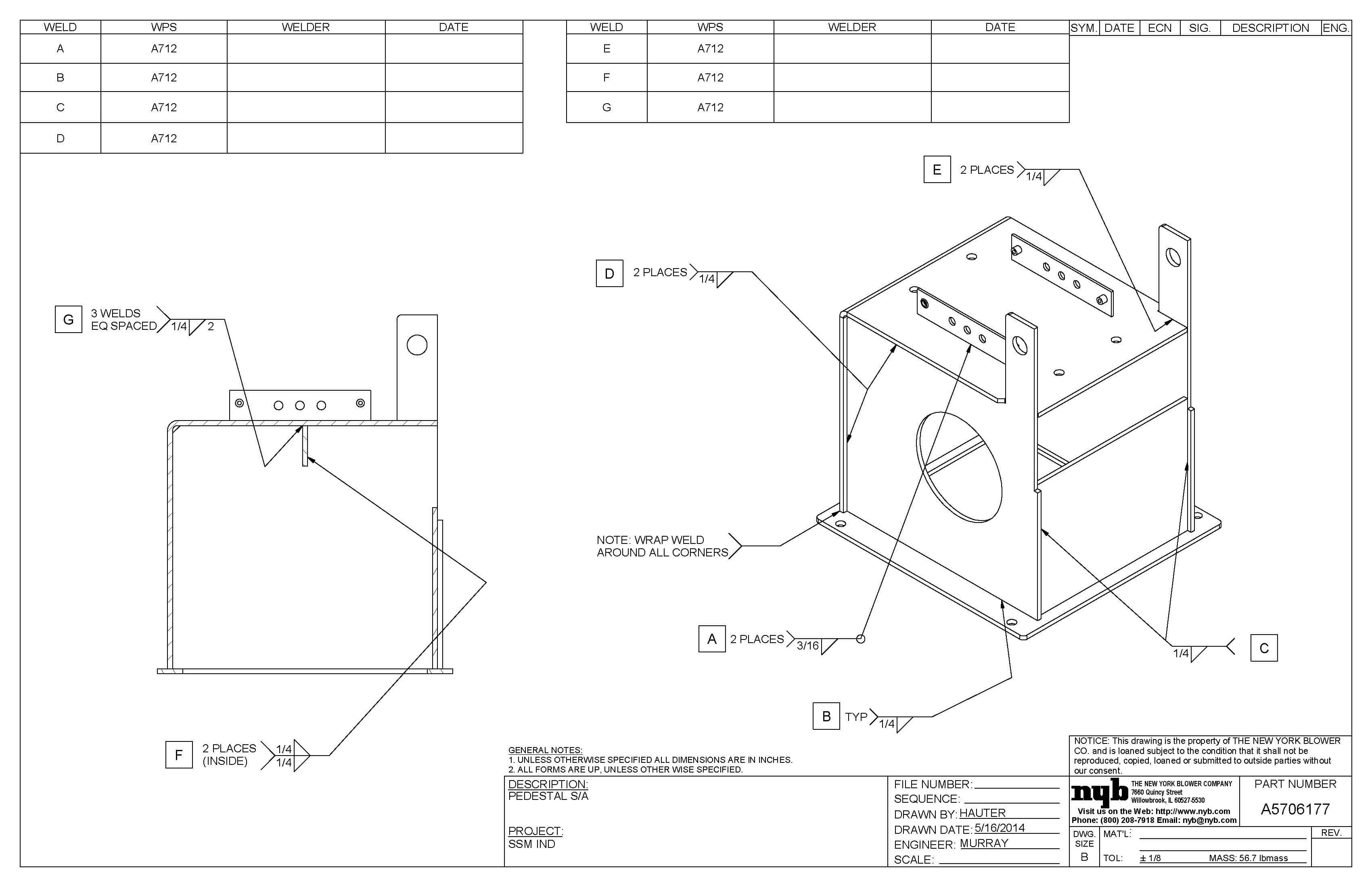
Weldment Drawing - The arrow line is connected to a leader line which is intersected with a horizontal reference line. Web if you insert autoballoons into a drawing view of a weldment and the drawing does not contain a cut list, you are prompted whether you want to create a cut list. Create a relative view for each part or for a set of parts. Web about press copyright contact us creators advertise developers terms privacy policy & safety how youtube works test new features nfl sunday ticket press copyright. Web there are basically two possible ways of creating drawings for each part: The reference line is a horizontal line that is used to align the other elements of the symbol. Web weld symbols come with an arrow that points to the direction of the drawing where a weld needs to be made. This method creates a new part that is linked to the original weldment. Weld symbols are a very useful way of communicating welding requirements from the design office to the shop floor. If you delete a cut list, all balloons related to the cut list change their item number to 1.
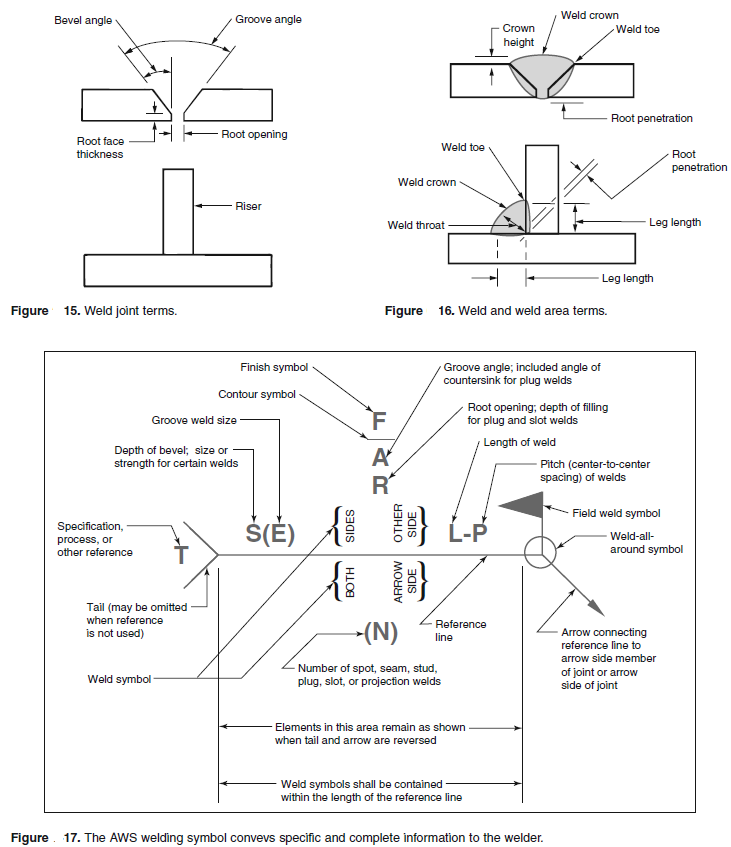
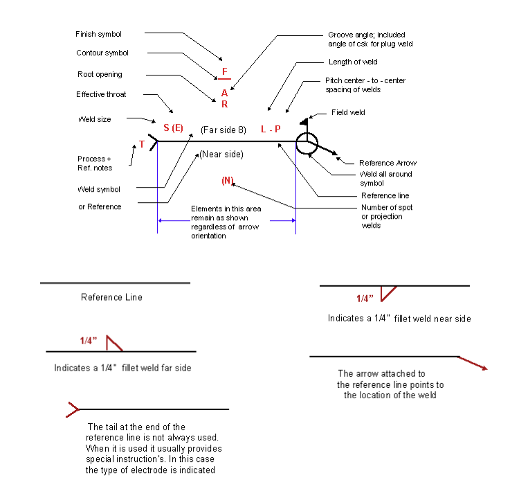
The v shape points upwards. The first method will create a new part that is linked to the original weldment, so it will get updated when the weldment sketches are updated. One needs to understand the welding processes, know how fatigue will impact the structures life, plan out joint design, understand how welds with deform the structure and ensure manufacturability. Web this is the basic solidworks weldments tutorial for beginners we will learn how to create 2d drawings of each structural member or profile and welding cut li. Web a weld symbol without a flag indicates that the weld is to be made in the shop. This video will help level up your 2d technical drawing documents look more pr. Bom table versus cut list. There are three main elements to a weld symbol: Web weld symbols are a key part of welding documentation, and understanding how to read weld symbols is critical for welders. The arrow line is connected to a leader line which is intersected with a horizontal reference line.
Web the symbol is very simple to draw because it only looks like a horizontal line and a v shape right in the middle of the line. Anyone can draw the symbol when putting together an engineering drawing. Web this is the basic solidworks weldments tutorial for beginners we will learn how to create 2d drawings of each structural member or profile and welding cut li. Right click a cut list item and select insert into new part. Web in a weldment part, the custom properties for the weldments feature and for the cut list represent a different list from the custom properties that are stored at the document level. Web modeling up a simple table using solidworks weldments is easy. Weld symbols are a very useful way of communicating welding requirements from the design office to the shop floor. This method creates a new part that is linked to the original weldment. This results in components that are parametrically linked to the weldment part. Spot weld diameter is 5, the number of spot welds is 10, and the interval is 30.
Welding detail in dwg file Cadbull
Web there are basically two possible ways of creating drawings for each part: The open circle at the arrow/reference line junction indicates a weld is to go all around the joint, as in the example below. Web modeling up a simple table using solidworks weldments is easy. Bom table versus cut list. The first method will create a new part.
Welding Terms and Symbols Basic welding symbols Engineersfield
Web a weld symbol without a flag indicates that the weld is to be made in the shop. Web creating a basic weldment drawing 4m 21s (locked) adding the cut list to the drawing 4m 13s (locked) adding in a weld table 4m 16s 5. Web if you insert autoballoons into a drawing view of a weldment and the drawing.

Weldment drawing a sheet for every body in one click CAD Booster
One needs to understand the welding processes, know how fatigue will impact the structures life, plan out joint design, understand how welds with deform the structure and ensure manufacturability. Web weld symbols come with an arrow that points to the direction of the drawing where a weld needs to be made. Anyone can draw the symbol when putting together an.
Welding Drawing at Explore collection of Welding
Figure 3 shows a drawing for a multibody weldment. Web about press copyright contact us creators advertise developers terms privacy policy & safety how youtube works test new features nfl sunday ticket press copyright. Web in today's video, western welding academy instructor, ronald maul, talks about the different types of weld drawings and how you'll use them while welding and..

SolidWorks Weldments tutorial Weld Bead and Symbols YouTube
However with weldments, there's a couple of other. The table shown is an inserted cut list. Using length and angle custom properties. Now you are on your way to making great weldment drawings. Create a relative view for each part or for a set of parts.

Weld. Scheme of Welding Two Parts. Vector Illustration. Stock Vector
Web weld symbols on drawings should be understood through the design and manufacturing pipeline, including shop floor personnel. Now you are on your way to making great weldment drawings. Web this makes the weldment drawing easier to read and understand. Web in a weldment part, the custom properties for the weldments feature and for the cut list represent a different.
Understanding the Welding Symbols in Engineering Drawings Safe Work
Web if you insert autoballoons into a drawing view of a weldment and the drawing does not contain a cut list, you are prompted whether you want to create a cut list. Web if you insert autoballoons into a drawing view of a weldment and the drawing does not contain a cut list, you are prompted whether you want to.

Frangus Drawings
The weld height is 3, with full welding around. Web this is the basic solidworks weldments tutorial for beginners we will learn how to create 2d drawings of each structural member or profile and welding cut li. Web weld symbols come with an arrow that points to the direction of the drawing where a weld needs to be made. There.
Weldment drawing a sheet for every body in one click CAD Booster
Create a relative view for each part or for a set of parts. The arrow line is connected to a leader line which is intersected with a horizontal reference line. Web this makes the weldment drawing easier to read and understand. It is essential that the 'rules' of the standard used are correctly applied by drawing office personnel. Web creating.

Solidworks Weldments tutorial Exercise 147 Weld Symbol Weld Bead
Weld symbols are a very useful way of communicating welding requirements from the design office to the shop floor. One needs to understand the welding processes, know how fatigue will impact the structures life, plan out joint design, understand how welds with deform the structure and ensure manufacturability. The reference line is a horizontal line that is used to align.
Web In A Weldment Part, The Custom Properties For The Weldments Feature And For The Cut List Represent A Different List From The Custom Properties That Are Stored At The Document Level.
The table shown is an inserted cut list. Anyone can draw the symbol when putting together an engineering drawing. The key is to just keep learning. Web creating a basic weldment drawing 4m 21s (locked) adding the cut list to the drawing 4m 13s (locked) adding in a weld table 4m 16s 5.
Web In Today's Video, Western Welding Academy Instructor, Ronald Maul, Talks About The Different Types Of Weld Drawings And How You'll Use Them While Welding And.
I don’t like this option. Web learn how to create a perfect weldment cutlist table drawing using solidworks. Inserisci la tua chiave di accesso per accedere al fantasyteam casinosistema. One needs to understand the welding processes, know how fatigue will impact the structures life, plan out joint design, understand how welds with deform the structure and ensure manufacturability.
Web This Is The Basic Solidworks Weldments Tutorial For Beginners We Will Learn How To Create 2D Drawings Of Each Structural Member Or Profile And Welding Cut Li.
The weld height is 3, with full welding around. However with weldments, there's a couple of other. Create a part per body. Figure 3 shows a drawing for a multibody weldment.
Create A Drawing Sheet Per Weldment Body (We Prefer This One) Option 1:
Web if you insert autoballoons into a drawing view of a weldment and the drawing does not contain a cut list, you are prompted whether you want to create a cut list. Create a relative view for each part or for a set of parts. The first method will create a new part that is linked to the original weldment, so it will get updated when the weldment sketches are updated. If you delete a cut list, all balloons related to the cut list change their item number to 1.