Draw Logic Gates
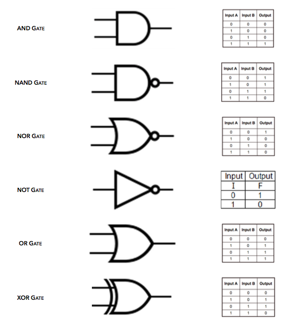
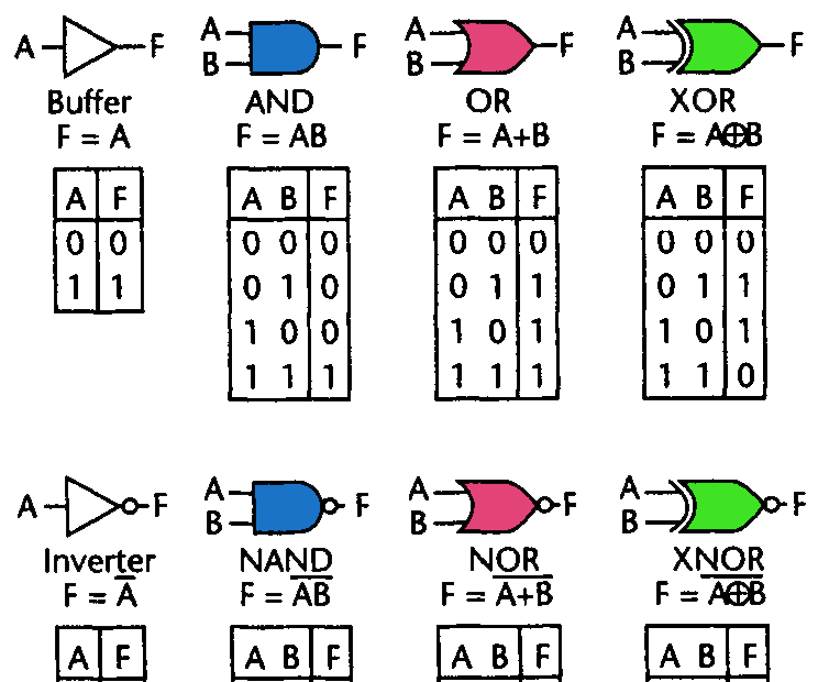
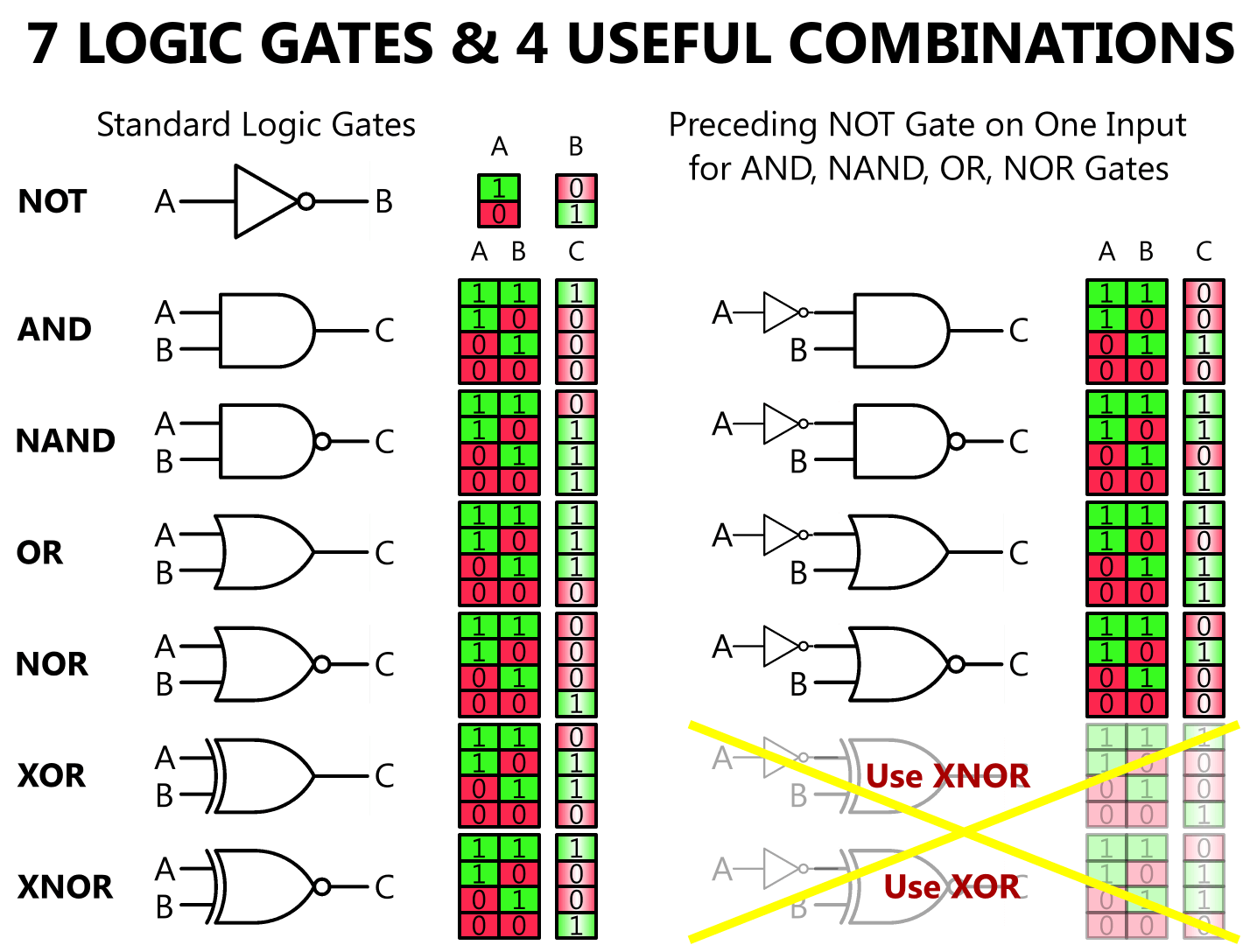
Draw Logic Gates - The following two are the derived logic gates used in digital systems: Types of basic logic gates. Draw the truth table and logic gate diagrams of the following functions: Types of basic logic gates. Not gates accept only one input digit. From simple gates to complex sequential circuits, plot timing diagrams, automatic circuit generation, explore standard ics, and much more. The truth table is used to show the logic gate function. Create subcircuits and use them all over your projects to help keep them organized. Web as well as a standard boolean expression, the input and output information of any logic gate or circuit can be plotted into standard boolean algebra truth tables to give a visual representation of the switching function of the system. The table used to represent the boolean expression of a logic gate function is commonly called a truth table.
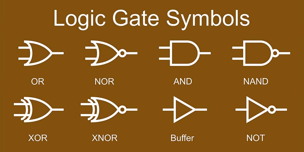
Draw the truth table and logic gate diagrams of the following functions: Graphical representation of logic gates. Right click connections to delete them. Each one has a different shape to show its particular function. Web a logic gate is a device that can perform one or all of the boolean logic operations and, nand, nor, not, or, xnor, and xor. Web computers often chain logic gates together, by taking the output from one gate and using it as the input to another gate. Web a digital logic gate is an electronic circuit which makes logical decisions based on the combination of digital signals present on its inputs. Web lightweight editor for creating and simulating logic gates. Web dive into the world of logic circuits for free! First you will need to learn the shapes/symbols used to draw the four main logic gates:
Select gates from the dropdown list and click add node to add more gates. Navigate to [new]> [electrical engineering]> [circuits and logic] step 3: In digital electronics, the following two logic gates are considered as universal logic gates: The not function is not a decision making logic gate like the and, or or gates, but instead is used to invert or complement a digital signal. Circuits enables computers to do more complex operations than they could accomplish with just a single gate. In this post you will practise drawing logic gates diagrams using the following logic gates: First you will need to learn the shapes/symbols used to draw the four main logic gates: Each one has a different shape to show its particular function. The table used to represent the boolean expression of a logic gate function is commonly called a truth table. From simple gates to complex sequential circuits, plot timing diagrams, automatic circuit generation, explore standard ics, and much more.
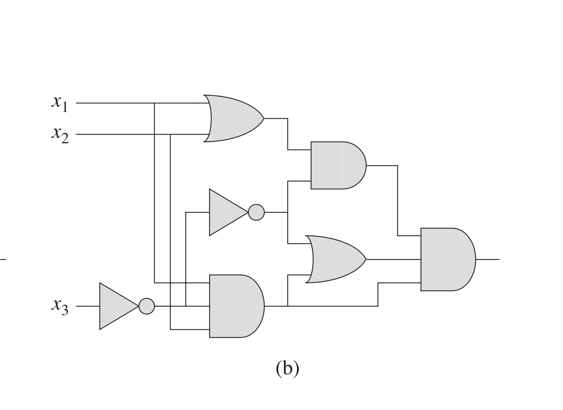
Circuit Diagram Using Basic Logic Gates
Outputs a '1') when both of its inputs are true, or false otherwise. Draw the truth table and logic gate diagrams of the following functions: Use multiple nand and/or nor gates.a+bab. First you will need to learn the shapes/symbols used to draw the four main logic gates: Drag from the hollow circles to the solid circles to make connections.

What are Logic Gates? Basic and universal gates YouTube
Web lightweight editor for creating and simulating logic gates. Web a free, simple, online logic gate simulator. All the logic gates have two inputs except the not gate, which has only one input. The not function is not a decision making logic gate like the and, or or gates, but instead is used to invert or complement a digital signal..
Basic Logic Gates Definition Truth Tables Examples Electrical
Web dive into the world of logic circuits for free! First you will need to learn the shapes/symbols used to draw the four main logic gates: When drawing a truth table, the binary values 0 and 1 are used. Select gates from the dropdown list and click add node to add more gates. In this lesson, we will further look.
Basic Logic Gates 7 Steps Instructables
These gates are used in combinational and sequential circuit design. Visual paradigm's logic diagram tool features a handy diagram editor that allows you to draw logic diagrams swiftly. First you need to learn the basic truth tables for the following logic gates: The and gate takes two inputs and evaluates to true (i.e. The table used to represent the boolean.
Circuit Diagram To Gates
Create subcircuits and use them all over your projects to help keep them organized. Web dive into the world of logic circuits for free! The not function is not a decision making logic gate like the and, or or gates, but instead is used to invert or complement a digital signal. Web a digital logic gate is an electronic circuit.

Different Types of Logic Gates
Graphical representation of logic gates. Design any complex logic gate circuit diagram with an extensive shape library consisting of standard symbols for logic gates. Logic gates in computer code. The and gate can be implemented by using two nand gates in the below fashion: Build and simulate your own circuits with logigator, a simple yet powerful online tool.
What is A Logic Gate Beginner's Guide EdrawMax Online
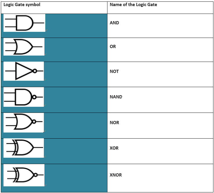
Types of basic logic gates. Web the basic logic gates are classified into seven types: Visual paradigm's logic diagram tool features a handy diagram editor that allows you to draw logic diagrams swiftly. Drag from the hollow circles to the solid circles to make connections. This circle is known as an “inversion bubble”.
Logic Gate ClassNotes.ng
Web in this post you will predict the output of logic gates circuits by completing truth tables. First you will need to learn the shapes/symbols used to draw the four main logic gates: In this lesson, we will further look at the different types of basic logic gates with their truth table and understand what each one is designed for..

Logic Gates Symbol CAD Block And Typical Drawing
Build and simulate your own circuits with logigator, a simple yet powerful online tool. The following two are the derived logic gates used in digital systems: Looking for a logic circuit tool? Web a free, simple, online logic gate simulator. All types of logic gate, except not, accept two binary digits as input, and produce one binary digit as output.
 Input Logic Gates with Truth Table.png)
Different Types of Logic Gates with Truth Table, Expression ETechnoG
Looking for a logic circuit tool? Design any complex logic gate circuit diagram with an extensive shape library consisting of standard symbols for logic gates. Web the basic logic gates are classified into seven types: Web a logic gate is a device that can perform one or all of the boolean logic operations and, nand, nor, not, or, xnor, and.
Web A Free, Simple, Online Logic Gate Simulator.
Web need to draw logic gate diagrams? The and gate can be implemented by using two nand gates in the below fashion: Types of basic logic gates. Build and simulate your own circuits with logigator, a simple yet powerful online tool.
Each One Has A Different Shape To Show Its Particular Function.
This article will introduce the concept of a logic gate as well as describe how each specific logic gate (or, and, xor, nor, nand, xnor, and not) works. All the logic gates have two inputs except the not gate, which has only one input. Navigate to [new]> [electrical engineering]> [circuits and logic] step 3: What is a logic gate?
Select Gates From The Dropdown List And Click Add Node To Add More Gates.
Web lightweight editor for creating and simulating logic gates. A cool term, but what does it mean? Right click connections to delete them. The truth table is used to show the logic gate function.
We Call That A Logic Circuit.
And, or, not, nand, nor, xor and xnor. In digital electronics, the following two logic gates are considered as universal logic gates: Graphical representation of logic gates. Select one logic gate diagram template to edit on it or click the [+] sign to start from scratch.