Standards For Engineering Drawings
Standards For Engineering Drawings - Web technical product documentation (tpd) — general principles of presentation — part 71: Engineering flow diagrams, representation of engineering components, lettering, units/ quantities, tolerancing, geometric product specifications, orthographic/axonometric representation, handling of computer based information. Since 2003 the iso 128 standard contains fifteen parts, which were initiated between 1996 and 2003. Web the engineering drawing rules are defined and embodied in the publications of standards organizations (for example, iso and asme ). Ensure compliance with industry standards, internal specifications, and regulatory requirements. This standard establishes the essential requirements and reference documents applicable to the preparation and revision of manual or computer generated engineering drawings and associated lists unless tailored by a. Proposed changes by dod activities must be submitted to the dod According to iso 29845:2011, drawing is “technical information, given on an information carrier, graphically presented in accordance with agreed rules and usually to scale.” It describes typical applications and minimum content requirements. Web the standard is intended to provide uniformity in drawing specifications and interpretation, reducing guesswork throughout the manufacturing process.
Popular internal searches in the engineering toolbox. [4] the name and contact information for the company producing or distributing the part. Proposed changes by dod activities must be submitted to the dod Stay abreast of engineering standards, regulations, and. Web one major set of engineering drawing standards is asme y14.5 and y14.5m (most recently revised in 2018). The basic drawing standards and conventions are the same regardless of what design tool you use to make the drawings. Web access a variety of standards: Asme y14.3m describes the accepted forms of single, multiple, and sectional views used on engineering drawings. Web asme y14.1 gives the asme standard size and format used in engineering drawings. This standard establishes the essential requirements and reference documents applicable to the preparation and revision of engineering drawings and associated lists.
It describes typical applications and minimum content requirements. It also provides requirements for use on engineering drawings, models defined in digital data files, and related documents. It describes typical applications and minimum content requirements. According to iso 29845:2011, drawing is “technical information, given on an information carrier, graphically presented in accordance with agreed rules and usually to scale.” Web the gsfc engineering drawing standards manual is the official source for the requirements and interpretations to be used in the development and presentation of engineering drawings and related documentation for the gsfc. This standard defines the types of engineering drawings most frequently used to establish engineering requirements. Popular internal searches in the engineering toolbox. (updated 15 aug 2017) subcommittee charters. Proposed changes by dod activities must be Lead the creation and development of detailed engineering drawings for various automotive components and systems.

Types Of Dimensions In Engineering Drawing at GetDrawings Free download
Engineering flow diagrams, representation of engineering components, lettering, units/ quantities, tolerancing, geometric product specifications, orthographic/axonometric representation, handling of computer based information. Web bs 8888 references standards covering all aspects of technical product documentation including: Proposed changes by dod activities must be The title block appears either at the top or bottom of an engineering drawing. This standard establishes the essential.
Introduction of ISO standards for technical engineering drawing
These apply widely in the united states, although iso 8015 (geometrical product specifications (gps) — fundamentals — concepts, principles and rules) is now also important. The basic drawing standards and conventions are the same regardless of what design tool you use to make the drawings. Web asme y14.24 2020 types and applications of engineering drawings standard. Technical drawings in general.
Engineering Drawings & GD&T For the Quality Engineer
Web the engineering drawing rules are defined and embodied in the publications of standards organizations (for example, iso and asme ). Web asme y14.24, “drawings types and applications of engineering drawings”, was adopted on 14 february 2000 for use by the department of defense (dod). Engineering flow diagrams, representation of engineering components, lettering, units/ quantities, tolerancing, geometric product specifications, orthographic/axonometric.
How To Prepare A Perfect Technical Drawing Xometry Europe
Web standard us engineering drawing sizes according ansi/asme y14.1 decimal inch drawing sheet size and formats below: Web the engineering drawing rules are defined and embodied in the publications of standards organizations (for example, iso and asme ). Through this method, y14.5 aims to improve quality, lower costs, and shorten deliveries wherever mechanical parts are designed or manufactured. The basic.

Drafting Standards Why a Good Drawing Numbering System is Important
Web the iso standards for technical drawings are found in a two volumes handbook: Engineering flow diagrams, representation of engineering components, lettering, units/ quantities, tolerancing, geometric product specifications, orthographic/axonometric representation, handling of computer based information. Read this first to find out crucial information about the drawing, including: [4] the name and contact information for the company producing or distributing the.
CME 475 Drawing Standards and Conventions
Since 2003 the iso 128 standard contains fifteen parts, which were initiated between 1996 and 2003. In addition, an individual company may have its own standards which supercede asme y14 to define conventions used by that company. Check the title block for basic information about the drawing. Proposed changes by dod activities must be submitted to the dod This standard.
Technical Drawing Standards A Brief History (BS 308 and all that)
Since 2003 the iso 128 standard contains fifteen parts, which were initiated between 1996 and 2003. Web bs 8888 references standards covering all aspects of technical product documentation including: Web one major set of engineering drawing standards is asme y14.5 and y14.5m (most recently revised in 2018). Simplified representation for mechanical engineering drawings Lead the creation and development of detailed.

2 7 single draw rules drawingonibispaint
Defines the types of engineering drawings most frequently used to establish engineering requirements. Web the standard is intended to provide uniformity in drawing specifications and interpretation, reducing guesswork throughout the manufacturing process. The title block appears either at the top or bottom of an engineering drawing. This standard defines the types of engineering drawings most frequently used to establish engineering.
Engineer Drawing Template
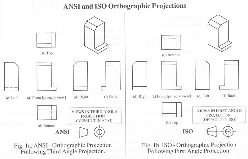
Stay abreast of engineering standards, regulations, and. Engineering standards, standard specifications & drawings, traffic control, fire standards and downtown area standards. Asme y14.3m describes the accepted forms of single, multiple, and sectional views used on engineering drawings. Through this method, y14.5 aims to improve quality, lower costs, and shorten deliveries wherever mechanical parts are designed or manufactured. Engineering flow diagrams,.
Iso Engineering Drawing Standards
Web the standard is intended to provide uniformity in drawing specifications and interpretation, reducing guesswork throughout the manufacturing process. Web the american national standards engineering drawing and related documentation practices (asme y14/ansi y14) contains the most widely accepted set of engineering drawing standards in the united states. It describes typical applications and minimum content requirements. Engineering standards, standard specifications &.
According To Iso 29845:2011, Drawing Is “Technical Information, Given On An Information Carrier, Graphically Presented In Accordance With Agreed Rules And Usually To Scale.”
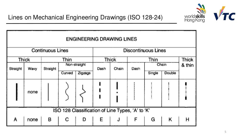
Asme y14.2 outlines the accepted line conventions and lettering used on engineering drawings. It also provides requirements for use on engineering drawings, models defined in digital data files, and related documents. Web iso 128 is an international standard (iso), about the general principles of presentation in technical drawings, specifically the graphical representation of objects on technical drawings. Web the gsfc engineering drawing standards manual is the official source for the requirements and interpretations to be used in the development and presentation of engineering drawings and related documentation for the gsfc.
Technical Drawings In General Iso Standards Handbook:
Read this first to find out crucial information about the drawing, including: Web the american national standards engineering drawing and related documentation practices (asme y14/ansi y14) contains the most widely accepted set of engineering drawing standards in the united states. Web asme y14 subcommittee charters engineering drawing and related documentation practices. Popular internal searches in the engineering toolbox.
The Basic Drawing Standards And Conventions Are The Same Regardless Of What Design Tool You Use To Make The Drawings.
Web technical product documentation (tpd) — general principles of presentation — part 71: This standard establishes the essential requirements and reference documents applicable to the preparation and revision of engineering drawings and associated lists. Engineering flow diagrams, representation of engineering components, lettering, units/ quantities, tolerancing, geometric product specifications, orthographic/axonometric representation, handling of computer based information. Proposed changes by dod activities must be submitted to the dod
In Addition, An Individual Company May Have Its Own Standards Which Supercede Asme Y14 To Define Conventions Used By That Company.
Web bs 8888 references standards covering all aspects of technical product documentation including: Web the iso standards for technical drawings are found in a two volumes handbook: The title block appears either at the top or bottom of an engineering drawing. It describes typical applications and minimum content requirements.